Design and Development of IoT IR Thermometer
[justify][center]
[/center][/justify]
[justify]Source:An office worker wearing a protective mask is screened with an infrared thermometer as he enters a building in New Delhi, India.(Photographer: Prashanth Vishwanathan/Bloomberg).[/justify]
[justify]Hello Makers lets collaborate on this platform to build a Contact-Less Thermometer. I know the fabrication (even the frugal fabrication) during this lockdown period may not be possible due to inaccessibility/non-availability of the required supplies but lets together work on the project upto “Digital Pre-Fabrication” stage. This may help us to fabricate the device soon after the lockdown period when supplies are available and it may also help those who have access to these supplies and facilities during lockdown period.[/justify]
[justify]So we all have seen this Contact-Less Thermometer atleast in news and social media videos under this pandemic situation due to COVID-19 spread. Doctors, Police men, Checking staff at places such as Airports, Hospitals, Roads and various other organizations, they are using it to check (screening) the people’s body temperature by just pointing this gun like structure at their forehead and getting the temperature without making any physical touch.[/justify]
[center]
[/center]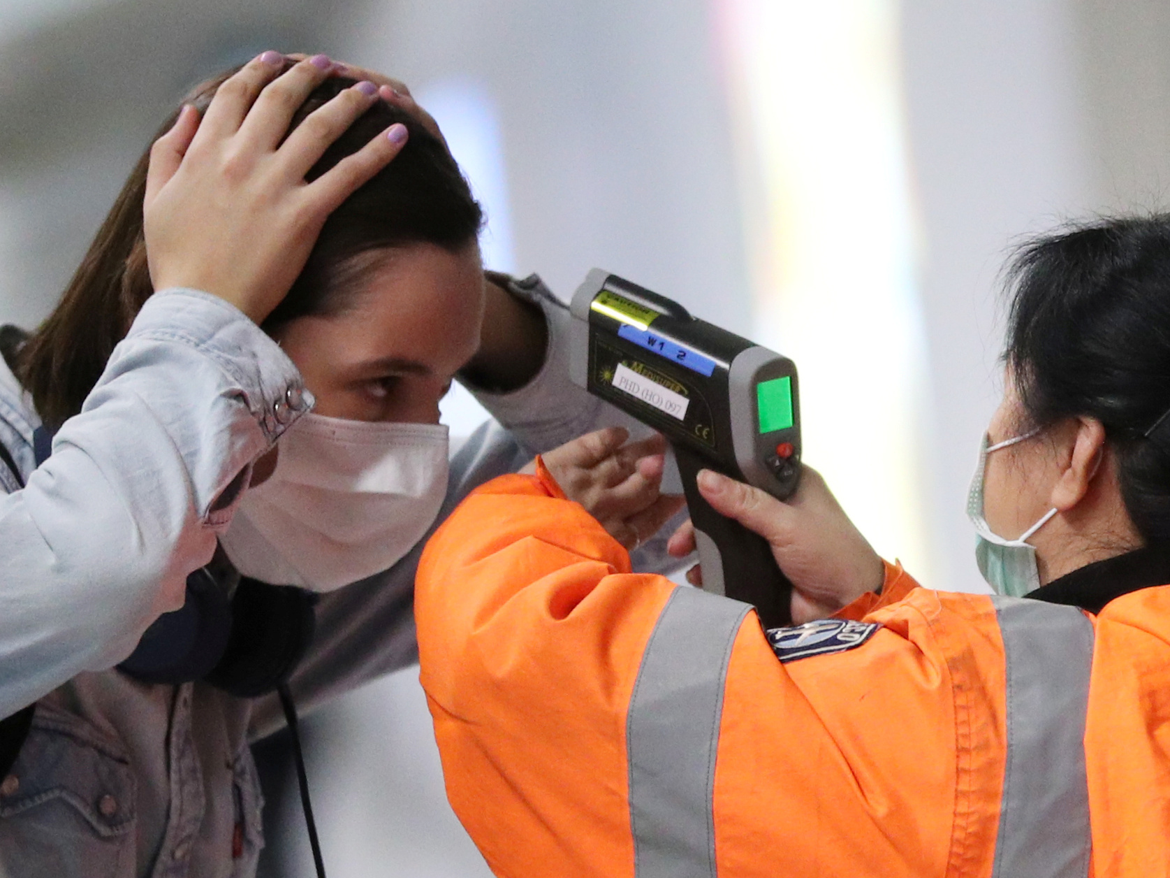
[justify][center]source :Mobile menu
[center]
[/center]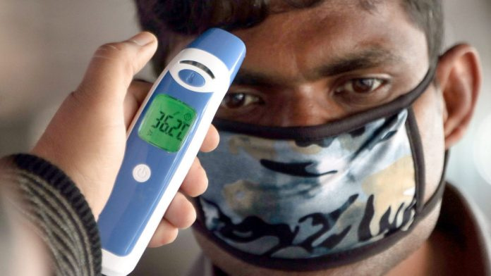
[justify][center]Source:India needs to ramp up COVID-19 testing, learn from South Korea & avoid US’ mistakes [/center][/justify]
[justify]It is very important to work on building of such devices and help other to build these devices by their own due to many reasons but below two are on the top in my views.[/justify]
[justify]* We need to increase the sampling rate by testing the body temperature of as many people, which requires large number of such device units.[/justify]
[justify]* Most Commercial companies of such products are trying to increase the price (price-gouging) which will at some rate making these products inaccessible.[/justify]
[justify]The contact-less thermometer (why we need contact-less, we all are aware) basically is a infrared thermometer which measures the surface temperature of an object. Anything with mass (eg: Human body, objects) emits some kind of energy in the form of heat ie infrared rays (IR). The infrared thermometer measures the difference between the surrounding IR and the IR coming from the object to determine the surface temperature of object itself.[/justify]
[justify]I will talk more technically on the working principle (must to know for developing the device) little later. One can read more about its working on these links:[/justify]
https://www.generaltools.com/blog/how-do-infrared-thermometers-work/
[justify]Now lets divide this device development into five sections and these are as follows:[/justify]
-
Sensor Selection and its Datasheet Reading.
-
Defining Features and Making Block Diagram.
-
Schematic and PCB Designing.
-
3D Encloser Designing.
-
Writing Code.
[justify]After confirming on the the circuit diagram we can work concurrently on last three sections (PCB designing, Writing code and encloser designing).[/justify]
Happy Development !
Section One: Sensor Selection and its datasheet Reading.
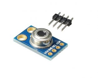
[justify]I found sensor MLX90614 suitable for our development as this itself is an IR Thermometer in a TO-39 package.[/justify]
[justify]On searching its availability online I found the lowest price from the following vendor.[/justify]
MLX90614 Datasheet.
Lets get into the details of this sensor.
MLX90614 (An IR Thermometer) 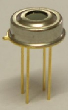
[justify]This sensor is basically the combination of IR Sensitive thermopile detector chip (part number: MLX81101) and signal conditioning ASSP (MLX90302), therefore it reduces all the core complexity for detecting and measuring the temperature and thus allowing us to focus only on reading the measurements form its memory location and putting it on a small display.[/justify]
-
In fact this IR Thermometer is also Factory Calibrated in wide temperature
range: -40°C…+125˚C for sensor temperature and
-70°C…+380˚C for object temperature. -
Measurement Resolution of 0.02*Celecius (This is the least measurement count).
-
High Accuracy of 0.5*Celcius.
Lets understand working of this sensor more technically as I stated earlier.
[justify]IR Thermometer focuses on the light coming from the object in the form of Infrared (IR) rays and channelize this IR radiation to the detector which is known as Thermopile. Inside this Thermopile IR radiation is turned into heat which then turned into electricity.[/justify]
[justify]The electric signal generated by IR Thermopile is passed to signal conditioning unit specially designed to process it. This unit basically amplify the signal, then covnvert it to stream of bits (using 17 bit ADC) and then fed it to DSP (digital signal processor) where signal is treated with FIR and IIR low pass filters for further reduction of the band width of the input signal to achieve the desired noise performance and refresh rate. The output of IIR filter is the measurement results.[/justify]
[justify]Based on this measurement results, the object temperature To and ambient temperature Ta is calculated and get stored in two dedicated location of RAM, which can be read via I2C interface or via the PWM digital output.[/justify]
[justify]The measured value is the average temperature of all objects in the Field Of View (FOV) of the sensor.[/justify]
Coming to operational Specifications
Operating voltage: 3v - 5v.
Operating current: 2mA.
Interfacing (Connecting) to Microcontroller/Arduino Board: There are two methods for it
- I2C Two-Wire Protocol.
- 10-bit PWM Output.
In this development we will use I2C Two-Wire Protocol.
Some very important point to be consider while development as per datasheet.
[justify]“ It is very important for the application designer to understand that these accuracies are only guaranteed and achievable when the sensor is in thermal equilibrium and under isothermal conditions (there are no temperature differences across the sensor package). The accuracy of the thermometer can be influenced by temperature differences in the package induced by causes like (among others): Hot electronics behind the sensor, heaters/coolers behind or beside the sensor or by a hot/cold object very close to the sensor that not only heats the sensing element in the thermometer but also the thermometer package.”[/justify]
[justify]Thus we need to carefully design the placement of electronics inside the encloser.[/justify]
[justify]We can also discuss other datasheet parameters which you think may be essential for our development, please feel free to write your query.[/justify]
Section 2: Defining Features and Making Block Diagram.
[justify]I have divide this section into two subsections and they are [/justify]
[justify]Section 2.1: Defining Features of this device.[/justify]
[justify]Section 2.2: Making Block Diagram.[/justify]
Section 2.1: Defining Features of this device.
[justify]To design and develop any device it is very important to define the purpose and features of that device. Purpose tells about what that device will actually do and features define the set of capabilities and services of the device required to achieve that purpose easily by the user.[/justify]
[justify]Purpose: This device will measure the surface temperature of an object and display it on the small screen and also provide the same data over internet if needed.[/justify]
Features:
- Non-contact, precise, fast, safe and easy to use.
[justify] There are many situations and applications where we need to measure the temperature of an object at distance. Such as measuring the human body temperature without touch it in the current situation of Epidemic COVID_19.[/justify]
[justify]And also in applications like measuring the temperature of hot and cold things in the kitchen, temperature of some moving part in some plant, detecting heat insulation breakages and many other commercial and industrial applications.[/justify]
[justify] Thus we require these measurements to be non-contact, easy, precise and fast enough. For which i have decide to use MLX90614 (IR Thermometer Sensor Module). We have already discussed the details of it and one can find it below.[/justify]
-
Readings on OLED Display.
To display reading and other data a small display is essential.
I have selected Oled 128x64 screen. -
IoT Enabled.
[justify]The data is also required over internet. One of it application is to generate Heat Map. [/justify]
[justify] Two methods to achieve this, either interface a WiFi module (use internet through the nearby WiFi network) or GSM/GPRS module (use mobile network through SIM) to the processing device.[/justify]
[justify]For this version i have decided to go with WiFi module.[/justify] -
Laser pointer for easy targeting the surface of an object.
[justify] laser pointer will provide the sight for accurate targeting the surface of an object for temperature measurement. [/justify]
[justify]Low power laser module is required for this.[/justify] -
Real Time Clock.
[justify] Date and Time stamp on the screen. This may be kept optional but i would like to add this.[/justify]
[justify] I have selected RTC DS3231.[/justify] -
Battery Powered.
[justify]Battery makes a device very convenient to use. [/justify]
[justify] For this version i am only thinking of using replaceable 9 volt battery and will wok on rechargeable battery with designing inbuilt battery management system (BMS) later (but yes very much needed).[/justify] -
Aesthetically designed encloser.
[justify]The encloser must be designed aesthetically handy, lightweight, compact and also order to accommodate all modules, PCB and components.[/justify] -
Encloser internal temperature measurement.
[justify] It is very important to also monitor the encloser internal temperature for the following reason.[/justify]
Section 2.2: Making Block Diagram.
[justify]With the features of the device we have also talked on the most of its components/modules to be used in this development. Now time to decide for its processing unit, I have figured out two options for this.[/justify]
- Arduino Pro Mini
- NodeMcu (ESP-12E)
[justify]lets look the block diagram of this device using both the options and then will get into details of each.[/justify]
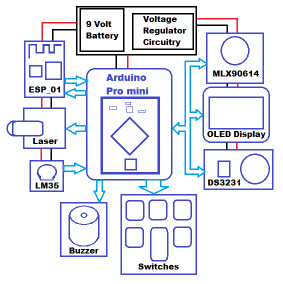
Block Diagram using Arduino Pro Mini as a Processing Unit
[center]
Block Diagram using NodeMCU (ESP-12E) as a Processing Unit.
[center]
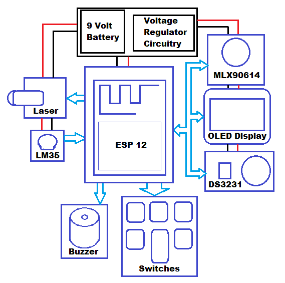
[justify]So the main difference we found in above two block diagrams is that with Arduino Pro Mini we need to interface external WiFi module (ESP 01) to communicate over internet.[/justify]
[justify]While with NodeMCU (ESP-12E), there is no requirement to interface any external WiFi module because it has inbuit WiFi.[/justify]
Lets also tabulate all important operational parameters of Arduino Pro Mini and NodeMCU (ESP-12E).
| Parameters | NodeMCU (ESP-12E) | Arduino Pro Mini |
|---|---|---|
| Bits System | 32-Bits System | 8-Bits System |
| Clock Freq | 80 to 160 Mhz | 16 Mhz |
| ROM | 4 MB | 128 KB |
| RAM | 128 KB | 2 KB |
| WiFi Unit | Inbuit WiFi | External WiFi Module Interface required. |
| Operating Voltage | 3.3v | 3.3v and 5v both options available but then Clock Freq will be 8 Mhz and 16 Mhz respectively. |
[justify]Here NodeMCU is much powerful as compared to Arduino Pro Mini. But Please note the specification of Arduino Pro mini is also good enough for this device development.[/justify]
To know more about Arduino Pro Mini and NodeMCU please refer to below links:
Lets also note each module power requirements and interfacings as per there datasheet.
| 1. MLX90614 |
|---|
| Operating Voltage 3v - 5v |
| Operating Current 2mA |
| Interfacing I2C (SDA, SCL) |
| 2. OLED Display (128 x 64) |
|---|
| Operating Voltage 3.3v |
| Operating Current 20mA |
| Interfacing I2C (SDA,SCL) |
| 3. DS3231 RTC |
|---|
| Operating Voltage 3v - 5v |
| Operating Current 70 – 150 uA |
| Interfacing I2C (SDA,SCL) |
| 4. Buzzer |
|---|
| Operating Voltage 3v - 5v |
| Operating Current 25mA to 35mA |
| Interfacing Digital pin to On/Off |
| 5. Laser Module |
|---|
| Operating Voltage 3v - 5v |
| Operating Current 40mA |
| Interfacing Digital pin to On/Off |
| 6. LM35 Temperature Sensor |
|---|
| Operating Voltage 5v |
| Operating Current 60uA |
| Interfacing Analog pin |
| Total Current Required by the above modules (let say it Total current of Modules) is: |
|---|
| 2mA + 20mA + 40mA + 35mA + 150uA + 60uA = 97.210 mA |
[justify]Now i would like to draw attention to very important parameter that is current requirement, all modules are same except Arduino needs external WiFi Module and NodeMCU has in built. [/justify]
[justify]So lets look for the figure of Overall current requirements for both the cases.[/justify]
| Overall Current Consumption = WiFi (RF Transmission) Current requirement + Total current of Modules |
Arduino Pro mini
In this case external Wifi Unit consumes around: 450 mA to 600 mA.
| Overall Current Consumption = 600 mA + 97.210mA =697.210mA |
NodeMCU
In this its inbuit WiFi consumes around: 80 mA.
| Overall Current Consumption = 80mA + 97.210mA = 177.210 mA |
[right]There is huge difference as per current consumption, Therefore NodeMCU (ESP-12E) is the perfect choice for this development.[/right]
[right]But we will design the device using both Arduino Pro Mini and NodeMCU.[/right]
Section 3: Schematic and PCB Design.
[justify]I would like to take few minutes to talk about the Electronics Computer Aided Design (ECAD) software which i am going to use here for designing schematic and PCB of our device.[/justify]
What is a Schematic?
[justify]Schematic is a symbolic representation of circuit diagram. It basically makes circuit diagram easy to read and share.[/justify]
What is a PCB Layout/Board ?
[justify]PCB Layout/Board is physical representation of circuit diagram. It is a actual board which will contain actual components.[/justify]
I am using software KiCAD
[justify]KiCad is an open source software suite for Electronic Design Automation (EDA). The programs handle Schematic Capture, and PCB Layout with Gerber output. The suite runs on Windows, Linux and macOS and is licensed under GNU GPL v3.[/justify]
You can visit KiCAD website for more details of it.
https://www.kicad-pcb.org/
[justify]The most interesting thing i like about this software is that it has integerated 3D viewer so allows us to check the 3D view of our designed board.[/justify]
So coming back to designing the schematic and PCB Board for our device.
As I earlier stated that we will design device using both Arduino Pro mini and ESP-12E.
The schematic using Arduino Pro Mini as main controller is given below.
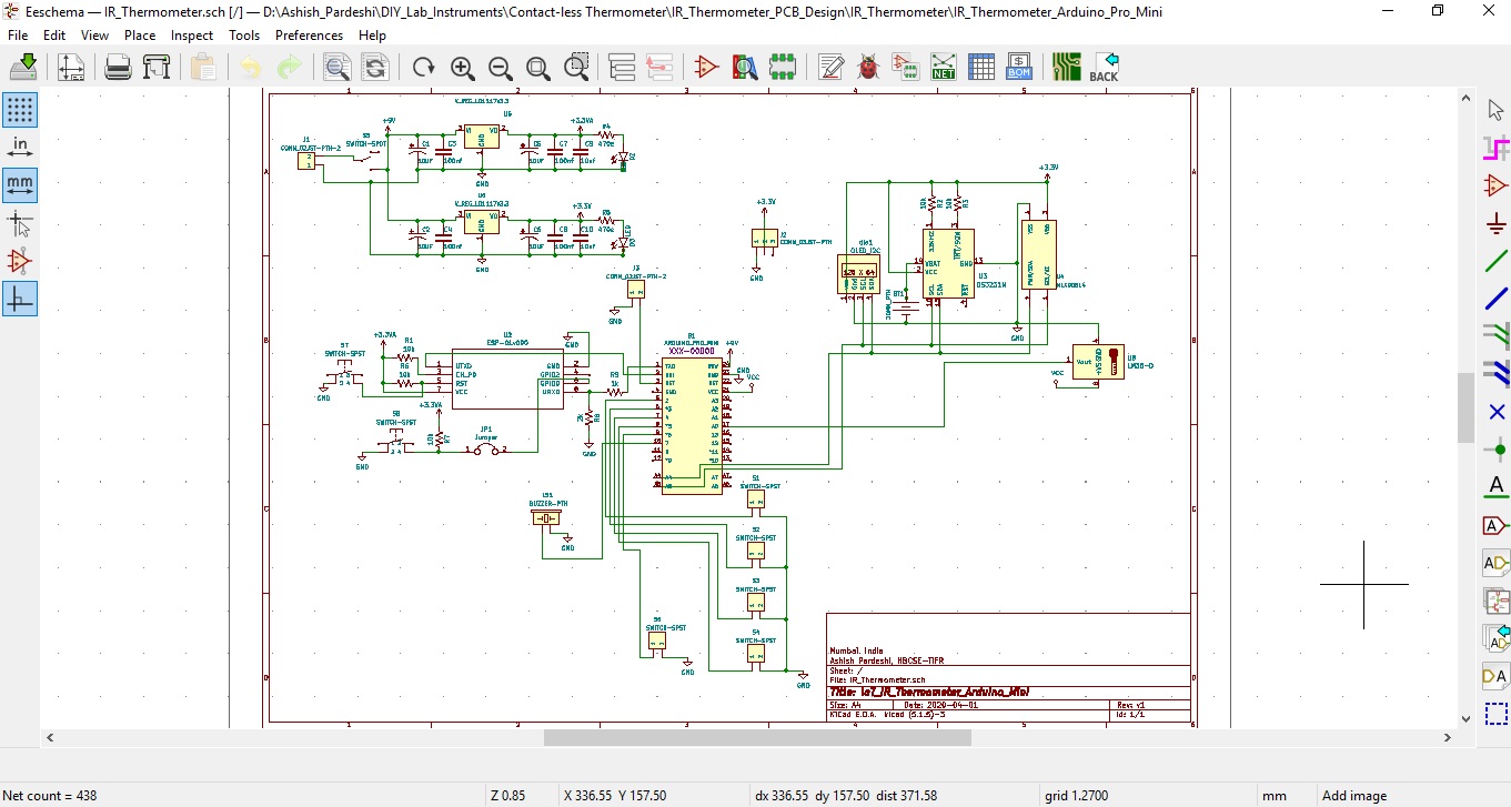
You can download the PDF of this schematic for more clear view given below.
IoT_IR_Thermometer_Arduino.pdf (51.4 KB)
Due to external WiFi unit (ESP01) and high power consumption as we have discussed in section 2, I have to decided to not to go for designing the board using Arduino Pro mini but will continue the development using ESP12E. But still i have loaded all the required components footprint in Layout so one can arrange and route them for the board. The 3D view that loaded components as per schematic is given below.
Top View
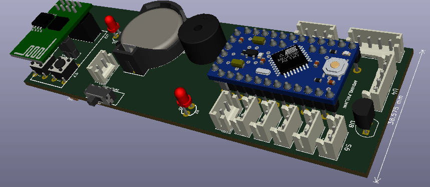
Bottom View

The schematic using ESP-12E (has integerated WiFi and low power consumption) as main controller is given below.
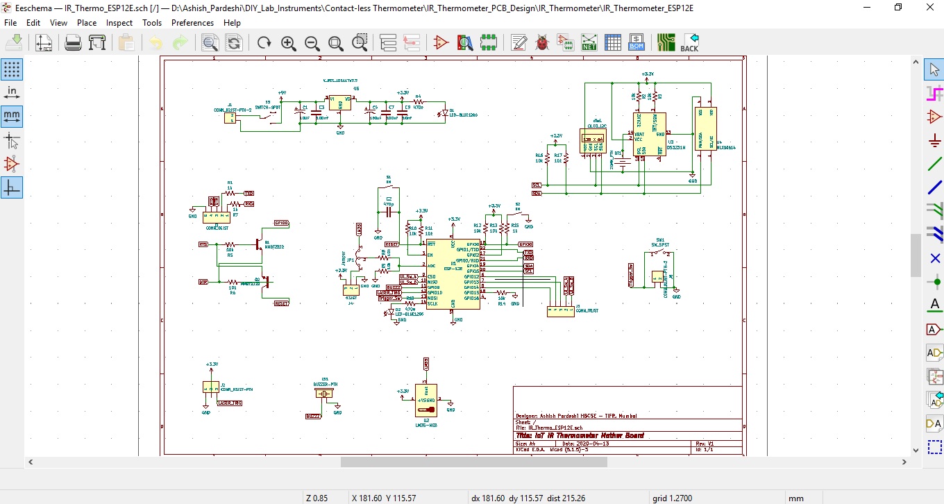
You can download the PDF of this schematic for more clear view given below.
IoT_IR_Thermometer_ESP12E.pdf (56.5 KB)
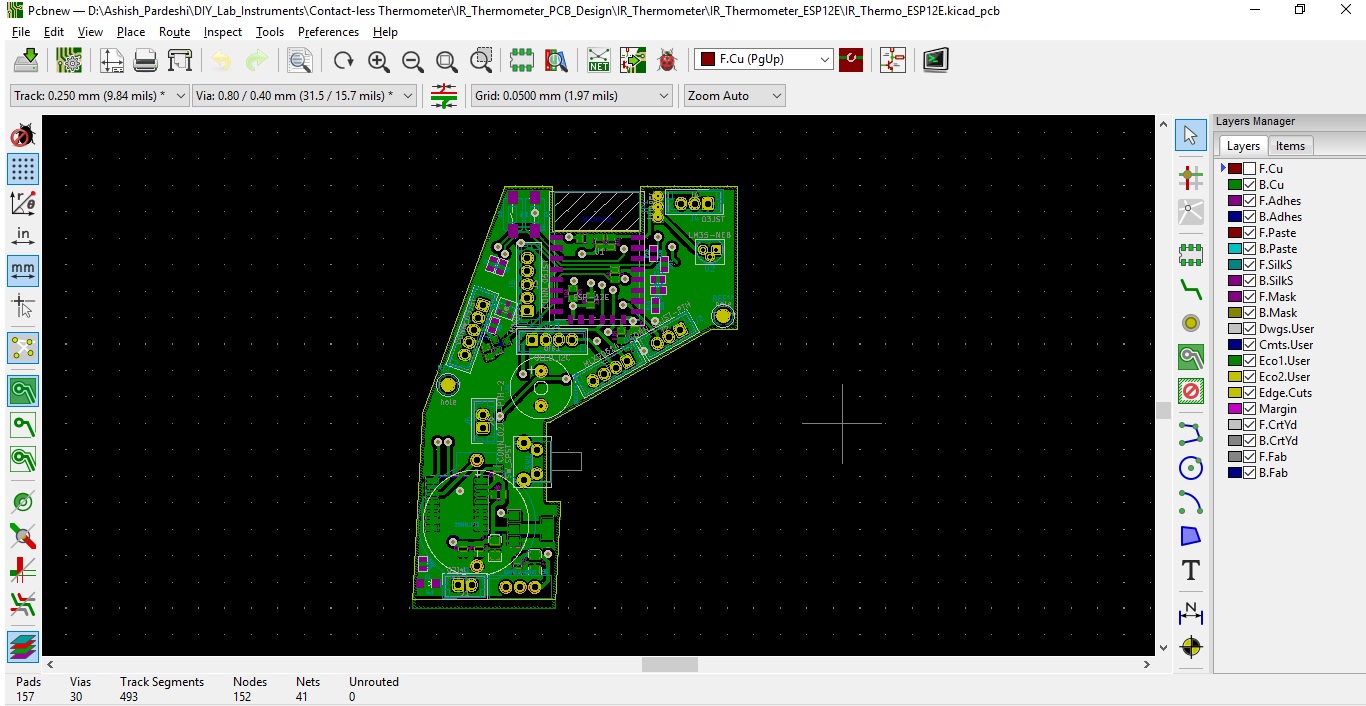
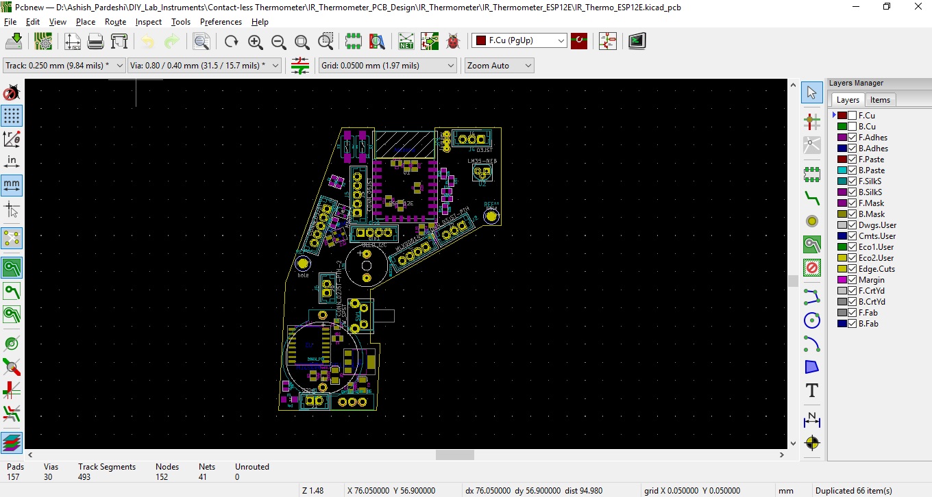
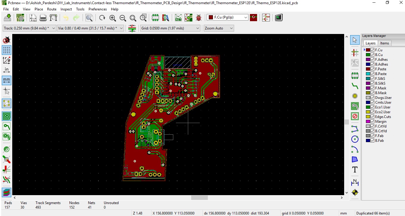
The PCB Layout using ESP-12E (has integerated WiFi and low power consumption) as main controller is given below.
Top Layer

Bottom Layer
Components View
Top and Bottom Layer Together
Lets look its 3D view
Top views
Bottom Views

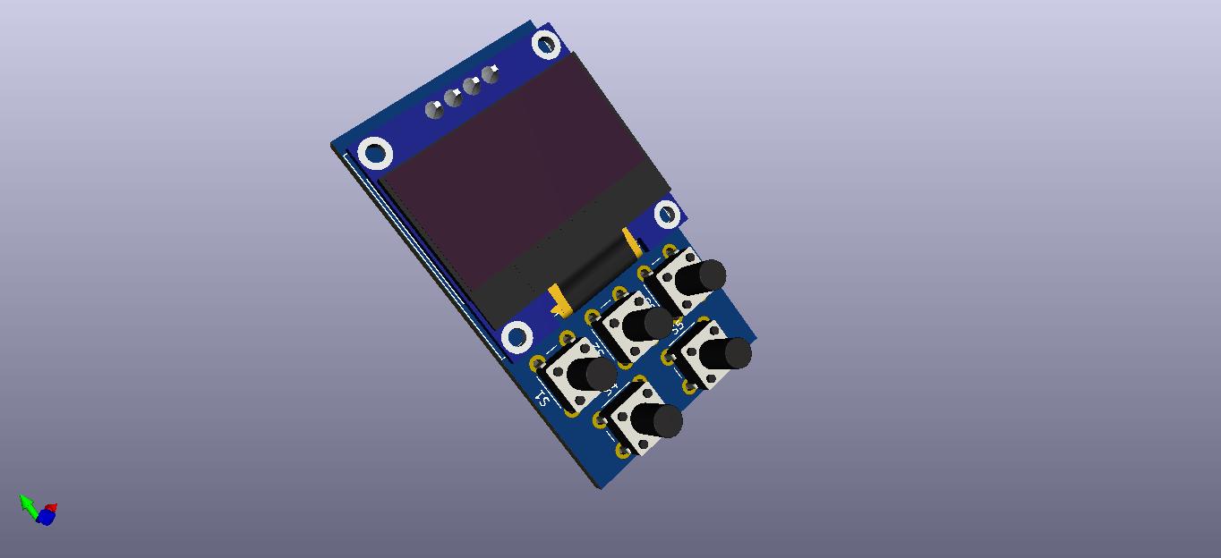
We also need to design User Interface (UI) PCB which contains a tiny display and few switches. The schematic for UI Board is given below.
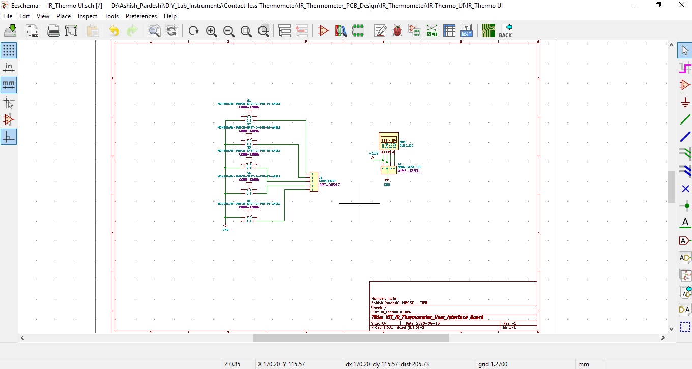
Download the Schematic PDF given below.
IoT_IR_Thermometer_UI.pdf (23.5 KB)
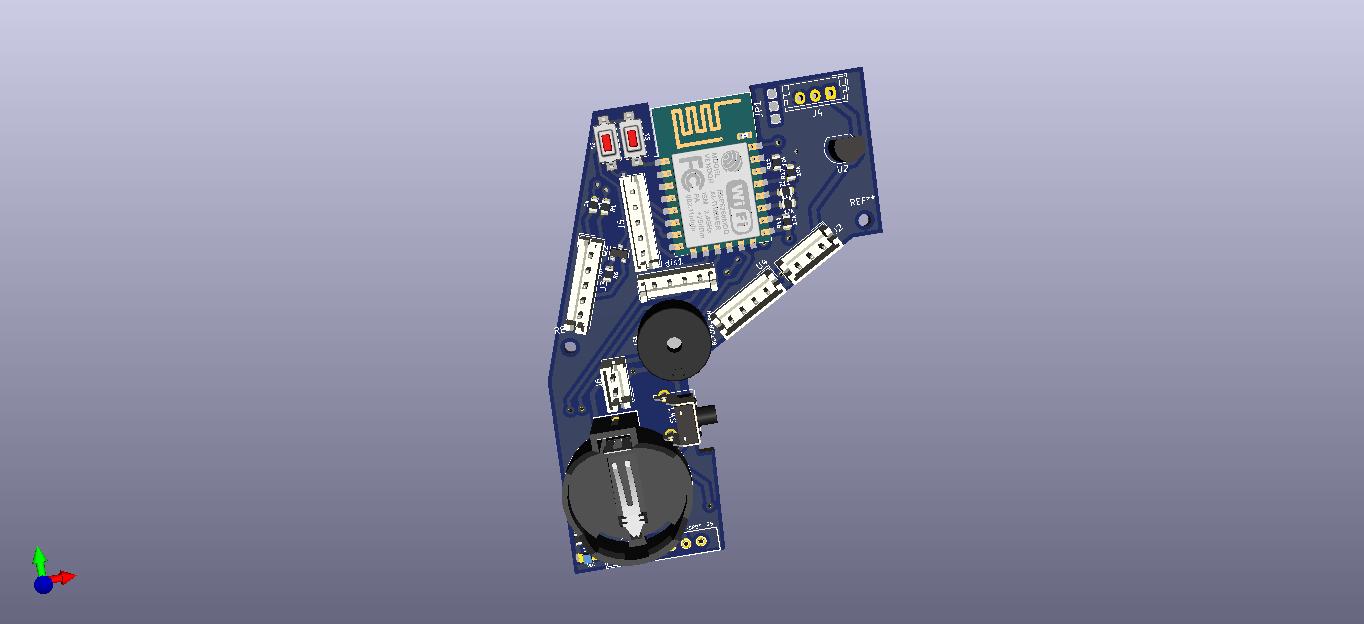
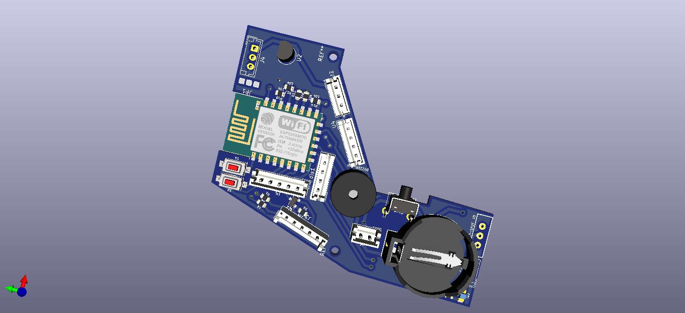
The PCB Layout for UI Board is given below.
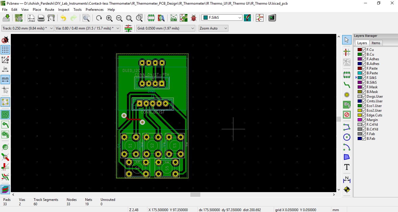
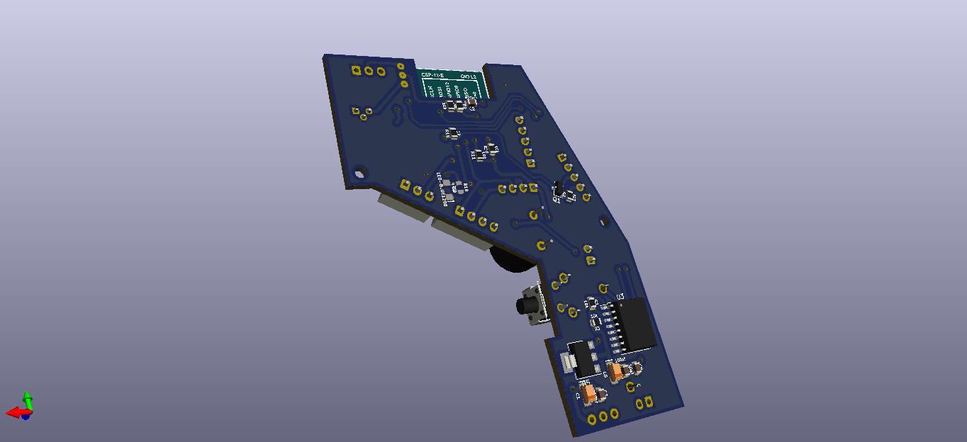
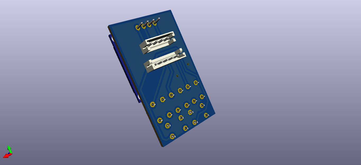
Lets also look its 3D view
Top View
Bottom View
So here we have completed Schematic and PCB Designing, I hope this section has provided you atleast the overview of Schematic and Layouts.
Happy Schematic and PCB Designing !
Section 4: Designing 3D Encloser
I have used FreeCAD, an open source software for mechanical CAD. This software provides various workbenches such as Sketcher, Part, Part Design and etc to work on 3D design.
For understanding the basics of FreeCAD workflow, please refer to following link:
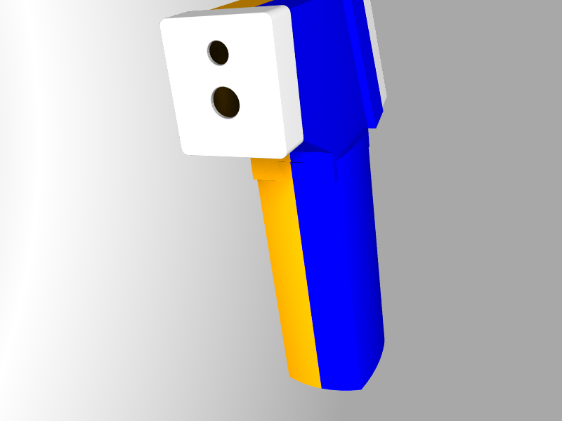
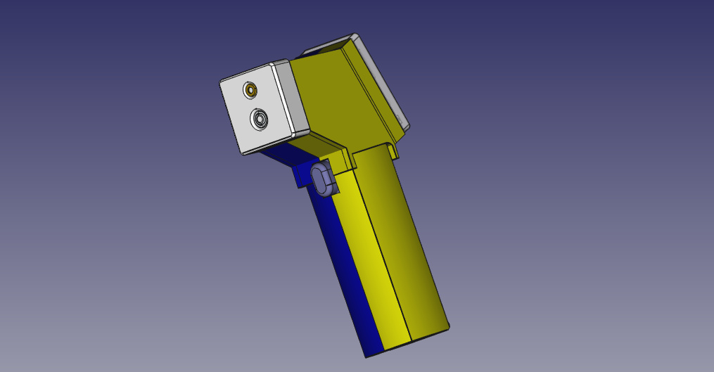
Okay so lets give a look to the rendered images of developed 3D encloser for IoT IR Thermometer write from begining to completion of design.
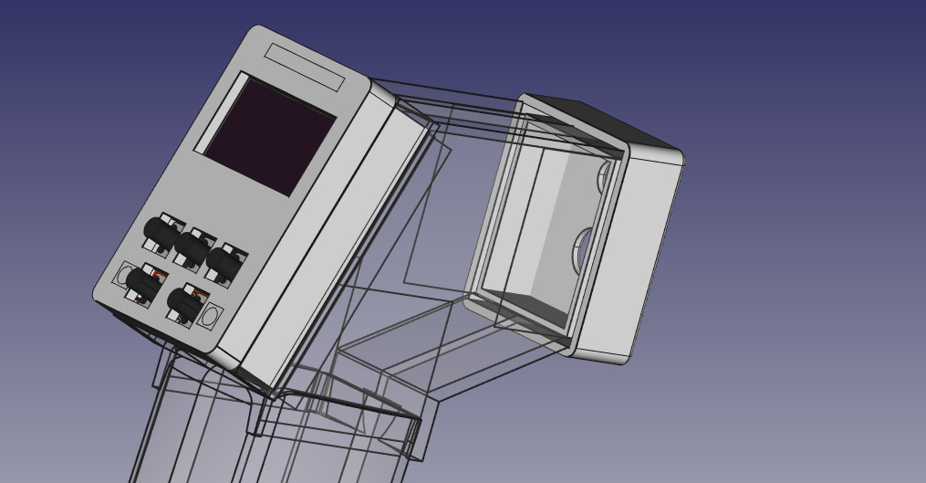
How the device will look?
[center]
[/center]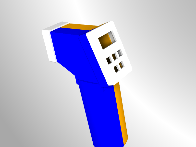
[center][/center]
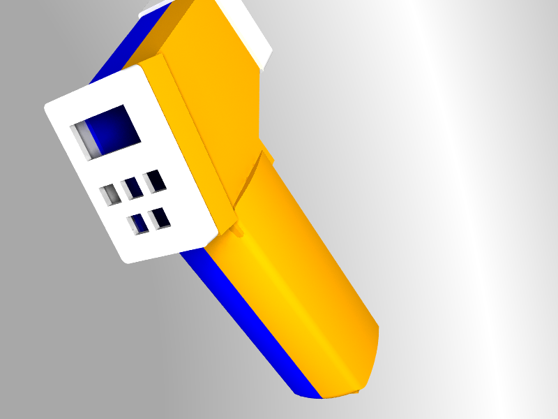
[center][/center]
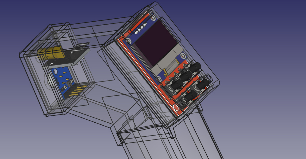
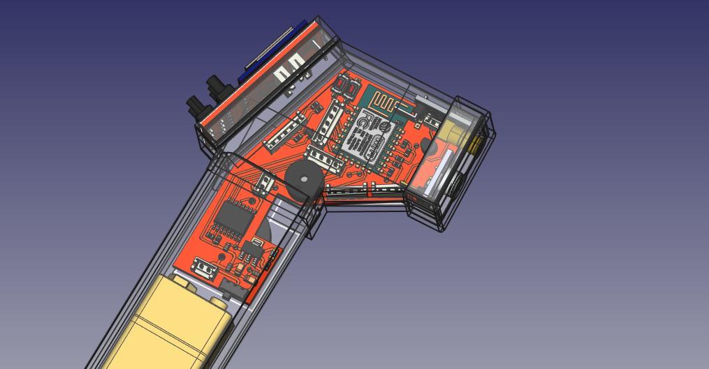
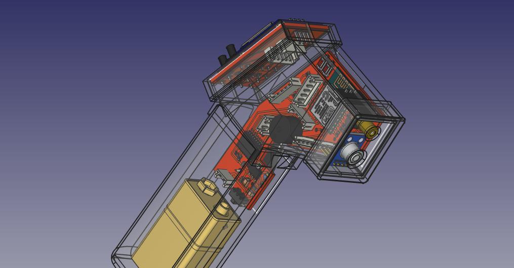
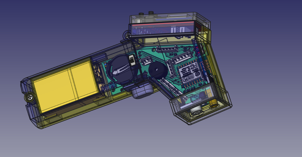
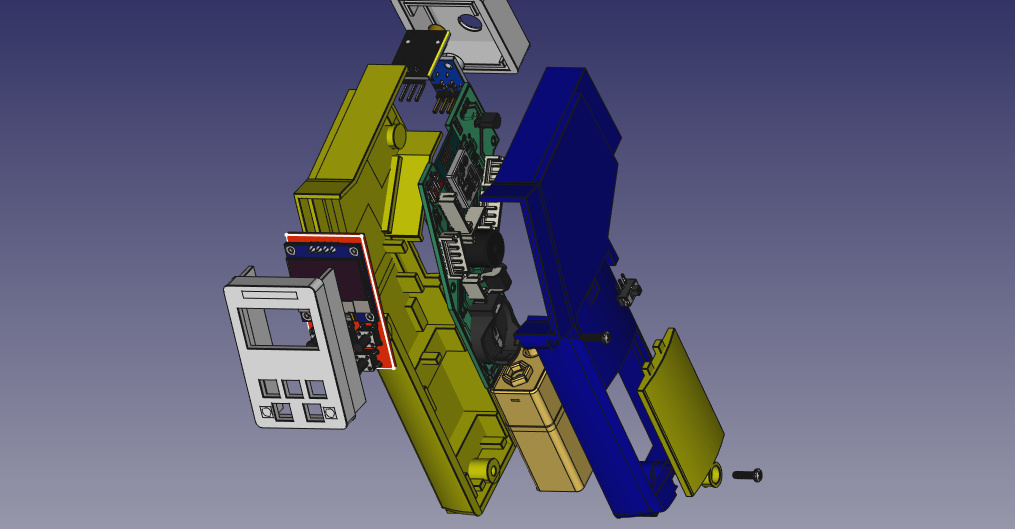
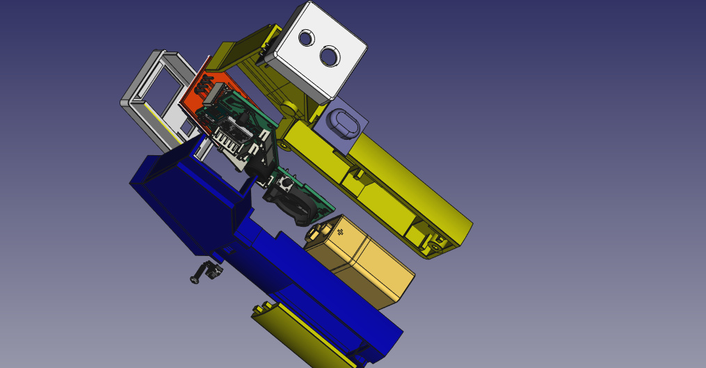
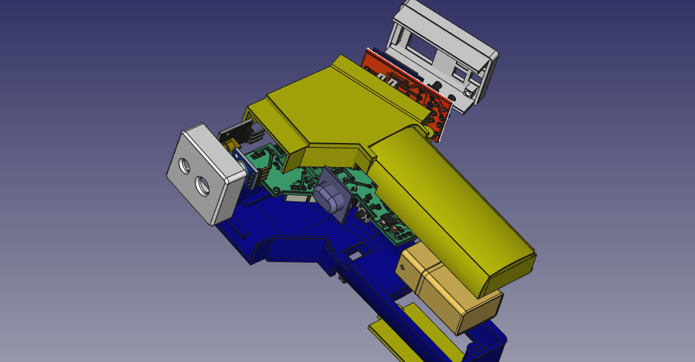
How the PCB boards will be placed inside encloser?
[center]
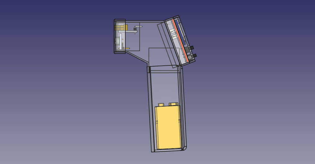
[center] [/center]
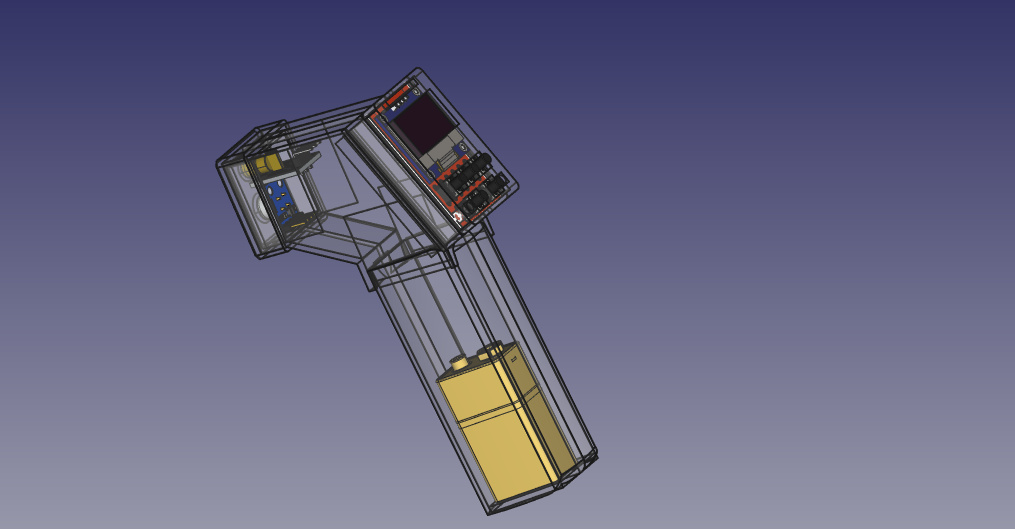
[center] [/center]
[center] [/center]
[center] [/center]
[center] [/center]

[center] [/center]
[center] [/center]
[center][/center]
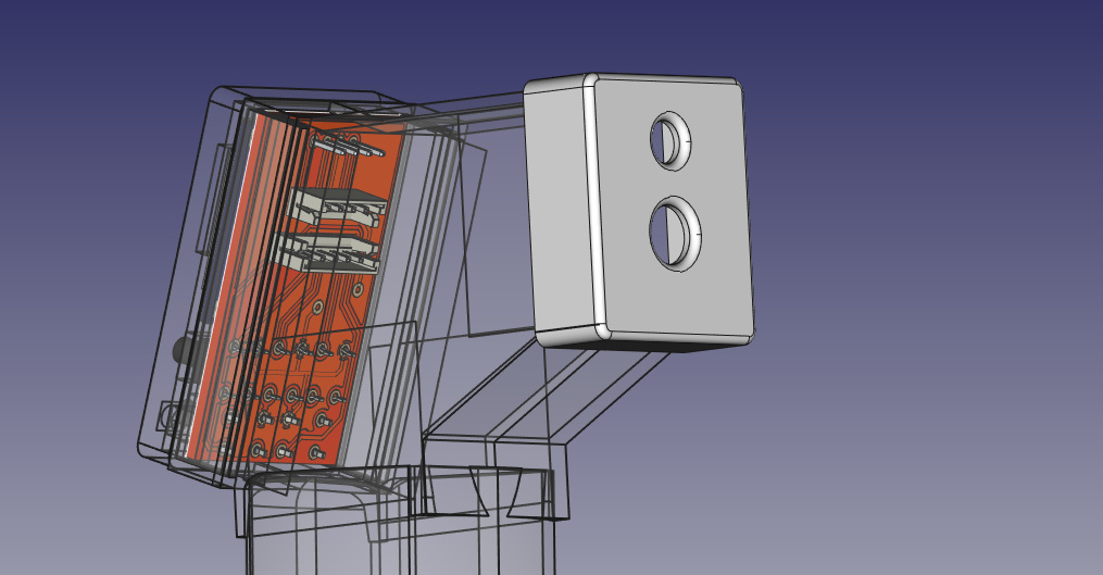
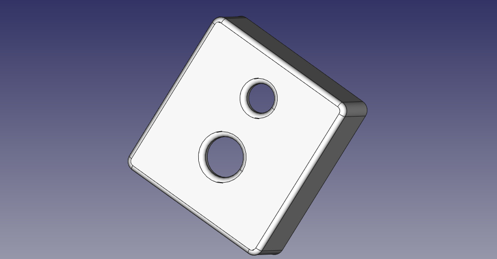
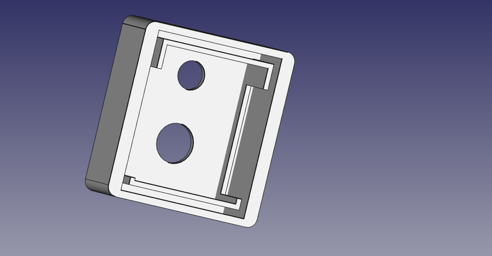
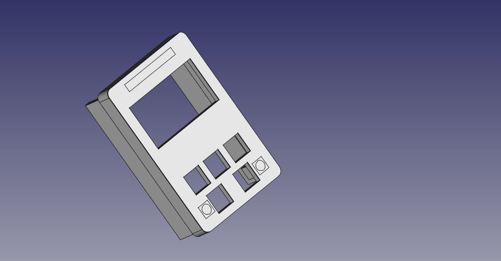
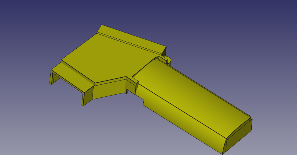
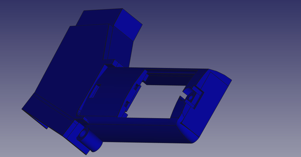
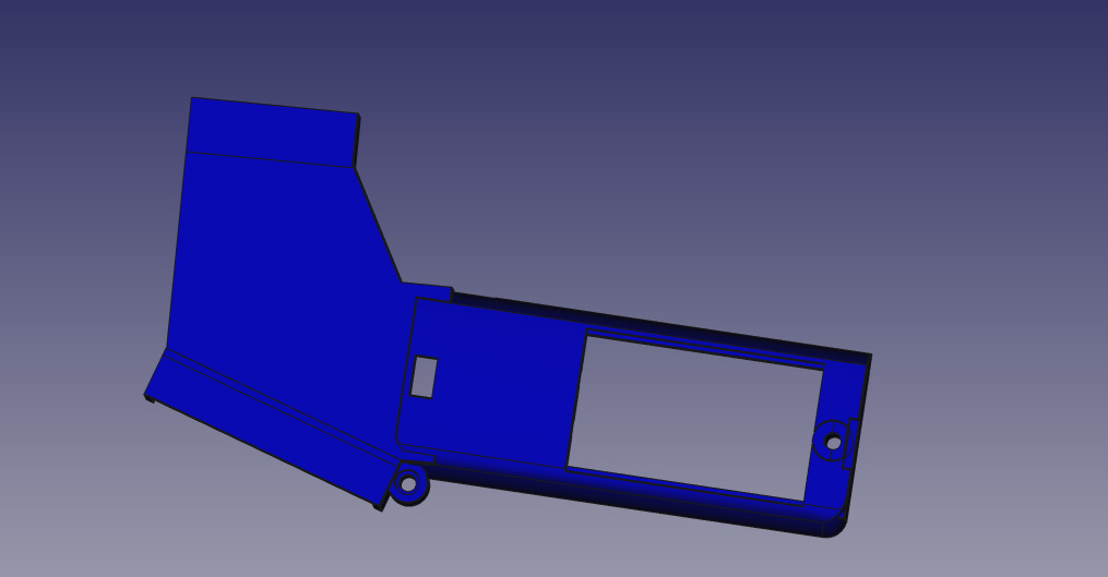
Looking at the Front Face (Sensor Face) design and Back Face (UI Face) design parts.
Front Face
Back Face

Adding the trigger Cap to the design.
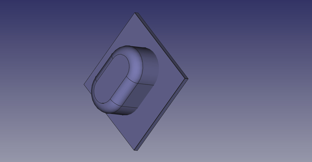
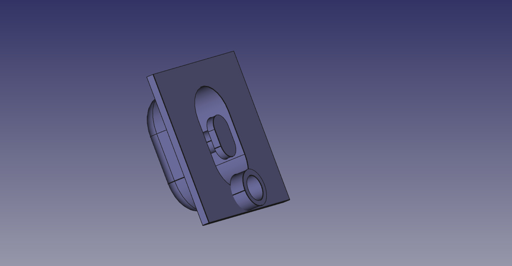
This is how i thought of Trigger Mechanism.
[center]

[center][/center]

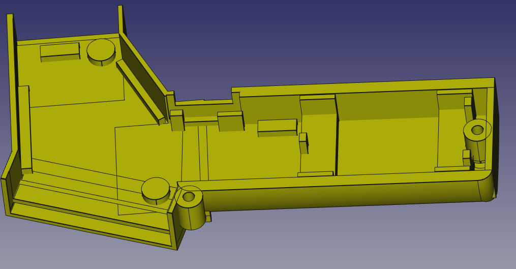
Making compartments for battery, stand ups for the board, battery Lid, screw joints.
[center]

[center] [/center]
[center] [/center]
[center] [/center]

[center] [/center]
[center][/center]
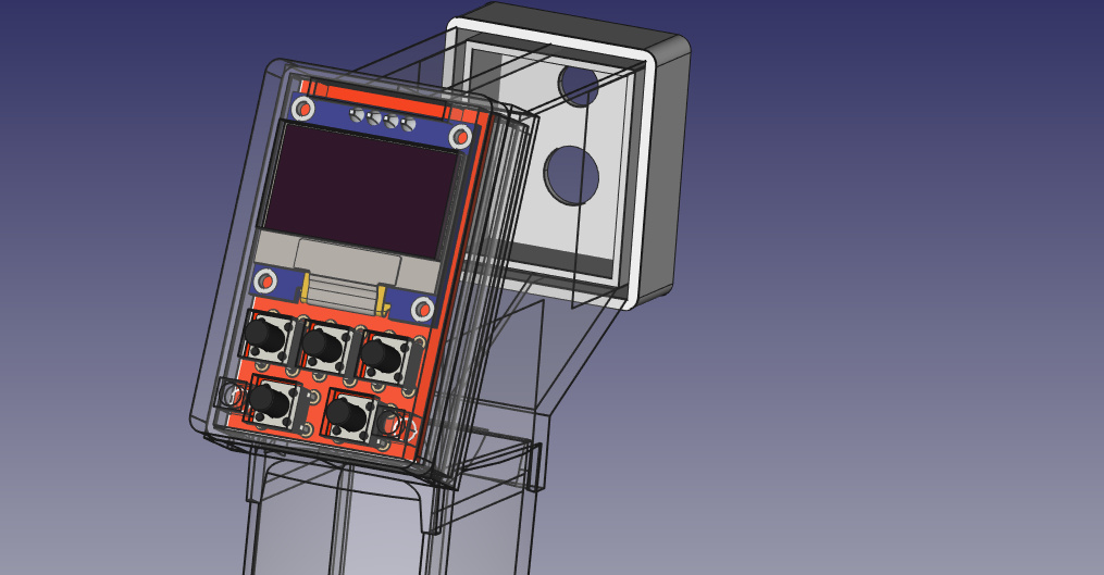
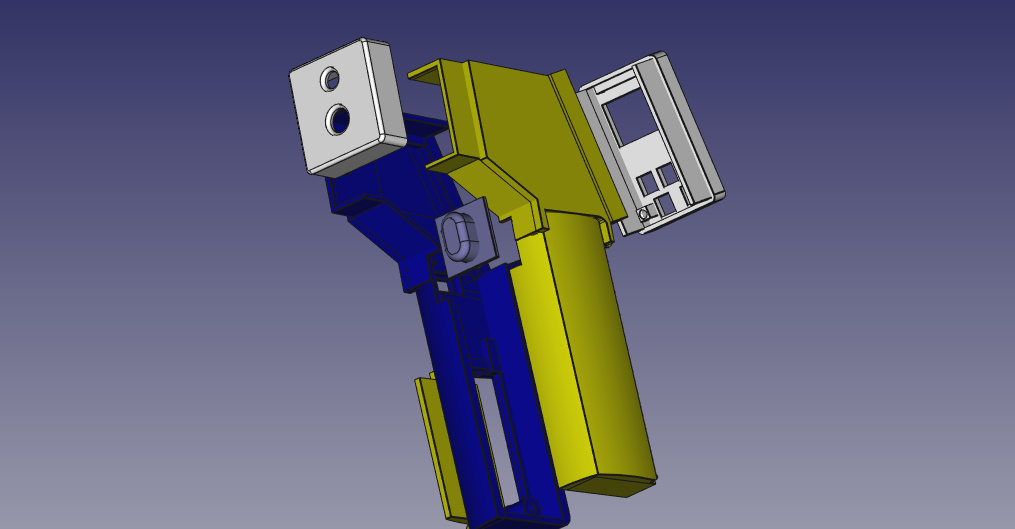
Completed design Images.
[center]
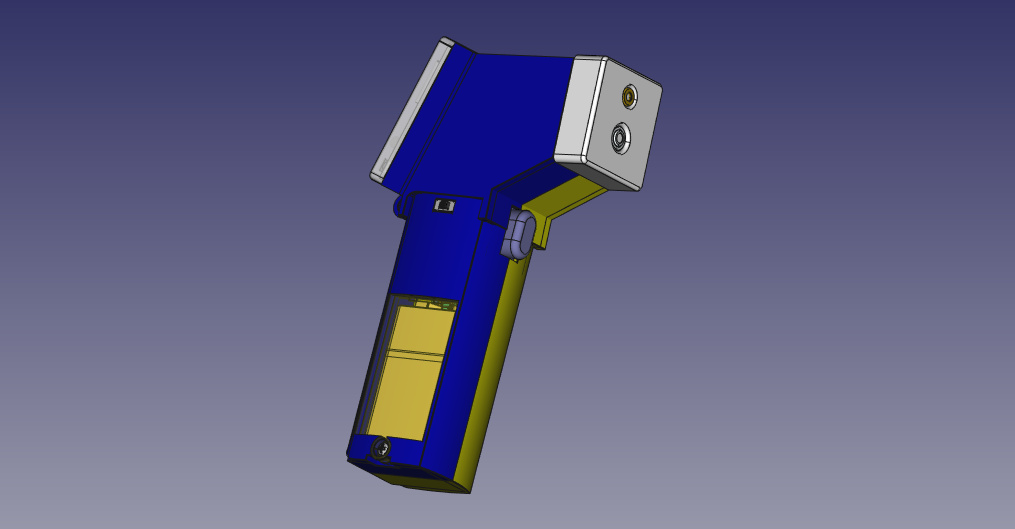
[center] [/center]
[center] [/center]

[center] [/center]

[center][/center]
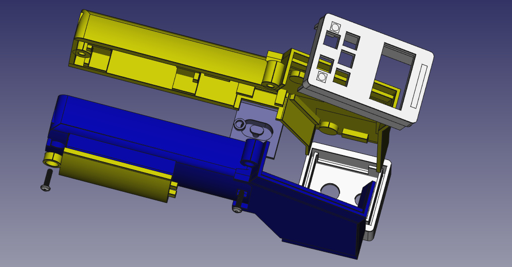
Assembling of designed parts
[center]
[/center]
[center] [/center]
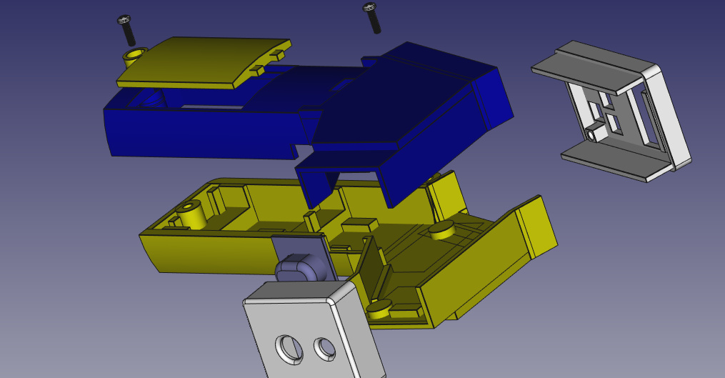
[center] [/center]
[center] [/center]
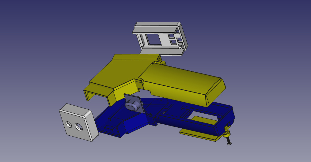
[center][/center]
[center]
[/center]
[center] [/center]
[center] [/center]
[center][/center]
This project is published as (CC BY-NC-SA 3.0), you can download all the source file related to PCB design and 3D design at the below github link.
Please note programming the device is still remaining for which i have decided to first fabricate the device and then writing a code for it meanwhile will keep the algorithm ready. Will publish the code as soon as we finish writing it after fabricating the device.
Download Electronics Bill of Material (BOM) PDF given below:
IOT_IR_Thermometer_Electronics_BOM.pdf (28.3 KB)
Download STl Files for 3D printing the encloser.
STL Files IoT_IR_Thermometer_v1.zip (1.9 MB)
Please feel free to ask any query.
Looking forward for collaboration, suggestions and modifications.