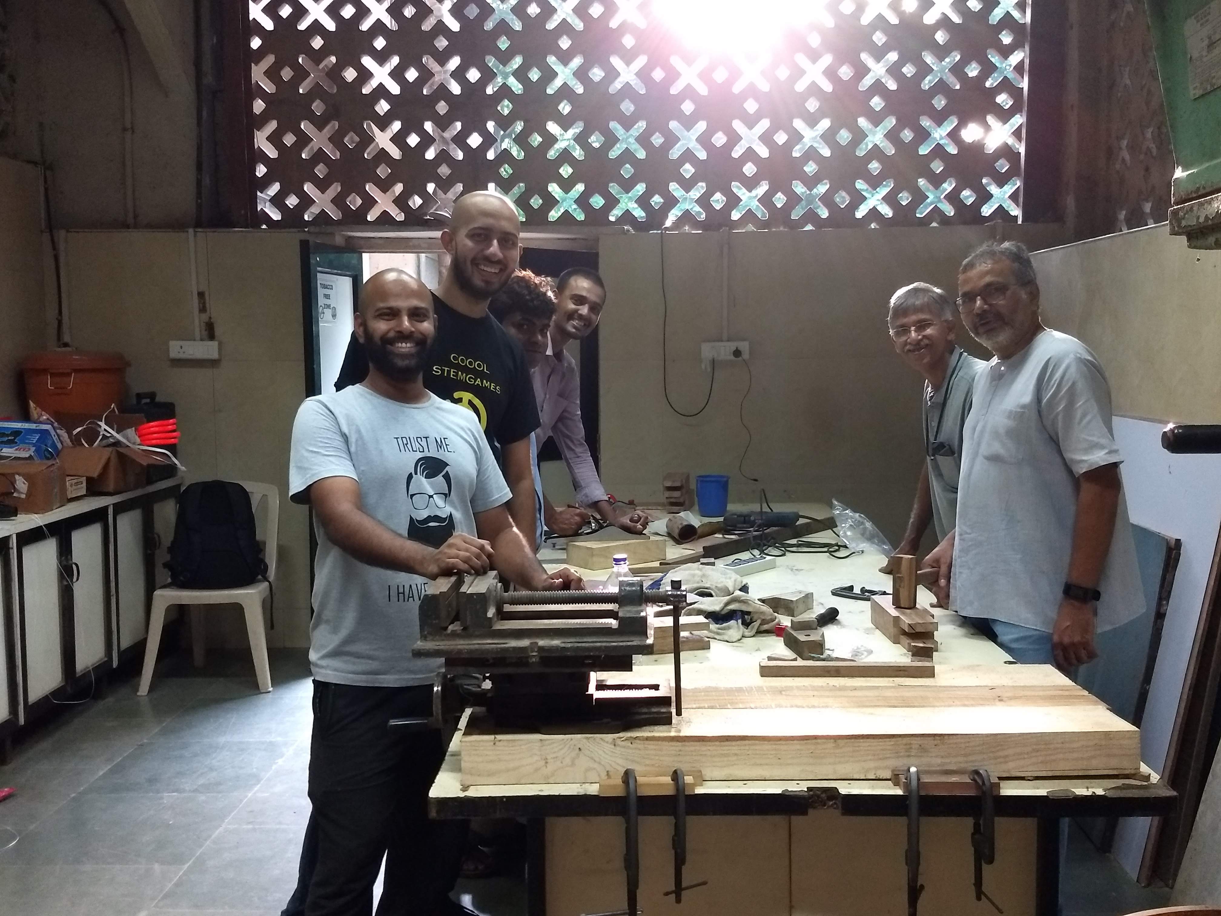
After the success of the last week’s wood-workshop, the MakerSpace team felt the need for a dedicated wood workbench.
The workbenches are designed to meet the needs of a modern-day woodworker and help in rapid prototyping/making of the artifacts. The bench is used by woodworkers to hold workpieces while they are worked by other tools. There are many different designs of benches, depending on the type of work and preference of the artist.
The main thing that distinguishes benches is the way in which the work is held in place. Most benches have more than one way to do this, depending on the operation being performed. The bench is solid and holds the work so that one can focus on doing. Vises are pre-mounted and there is the versatility of the vice location which permits ease of both left or right-handed use, clamping on both ends or dual clamping on the front. The benchtop is built to last for a lifetime of normal use. The benches can be designed with or without the storage cabinet.
Ready-made designs are costly and if we can come up with a frugal and better version based on our own customized needs, that will be really useful. We hope that the design can serve as a low-cost template which can further be replicated by maker spaces such as Atal Tinkering Labs etc and instill the DIY Spirit.
Here we will keep documenting the project as it takes shape - including things that worked, goof-ups and joy in the process!
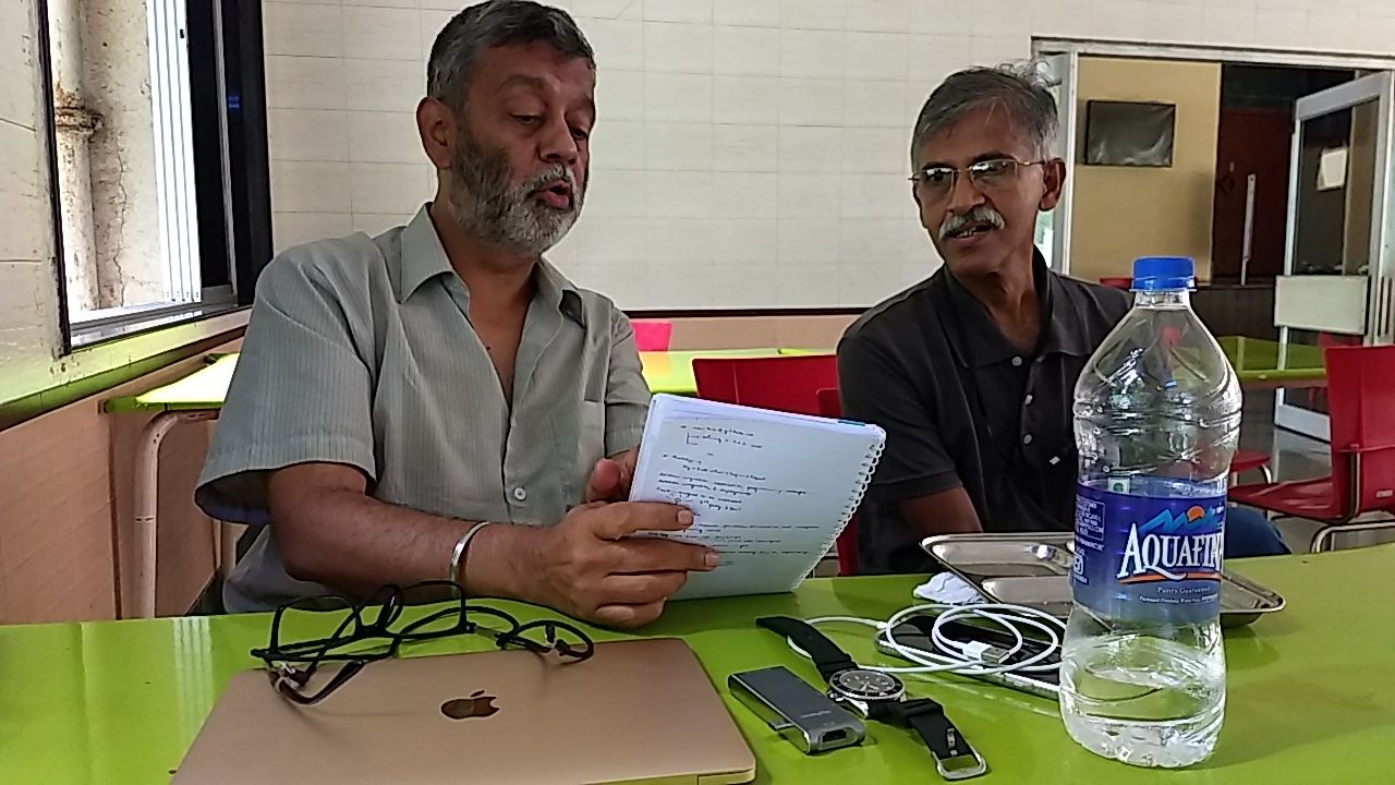
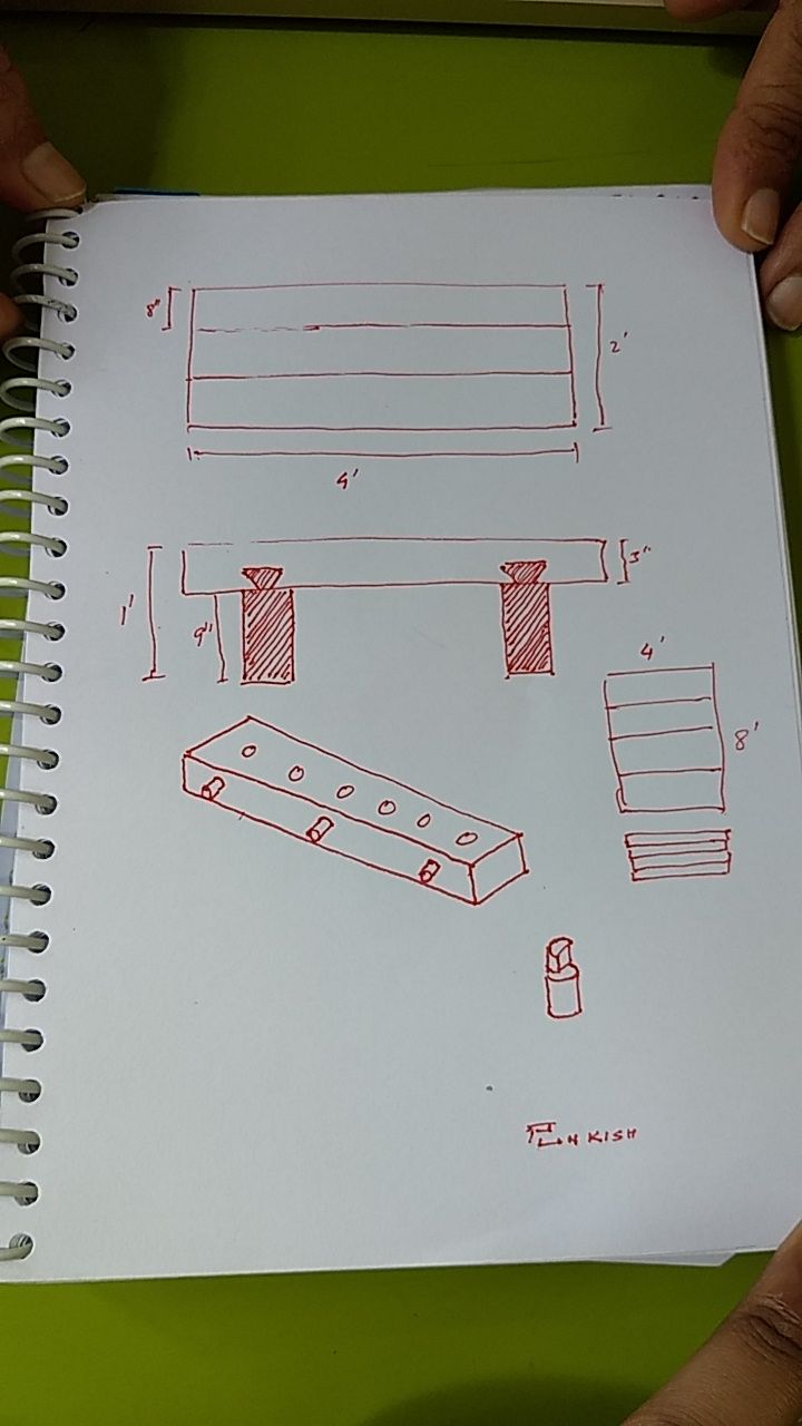
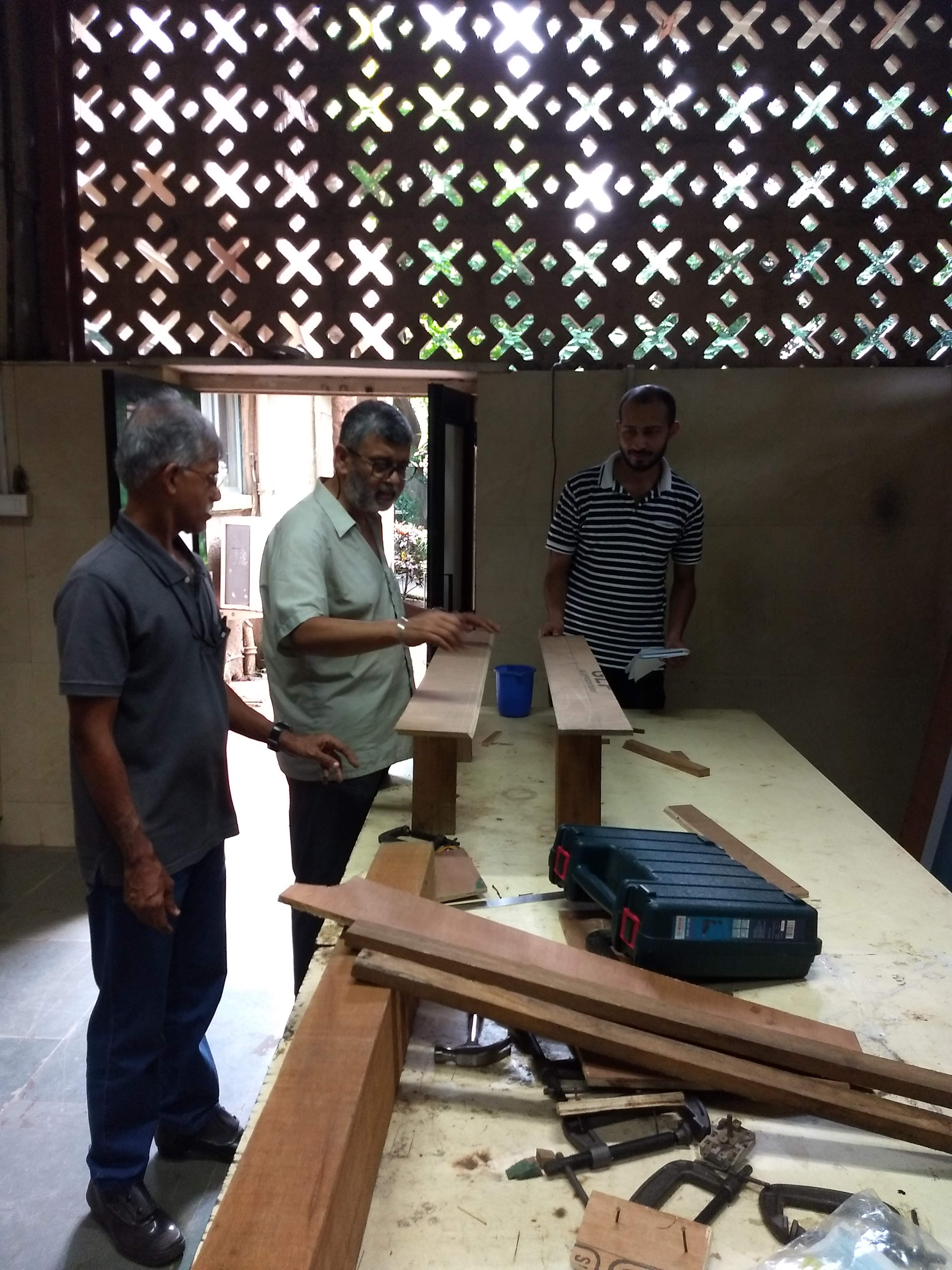
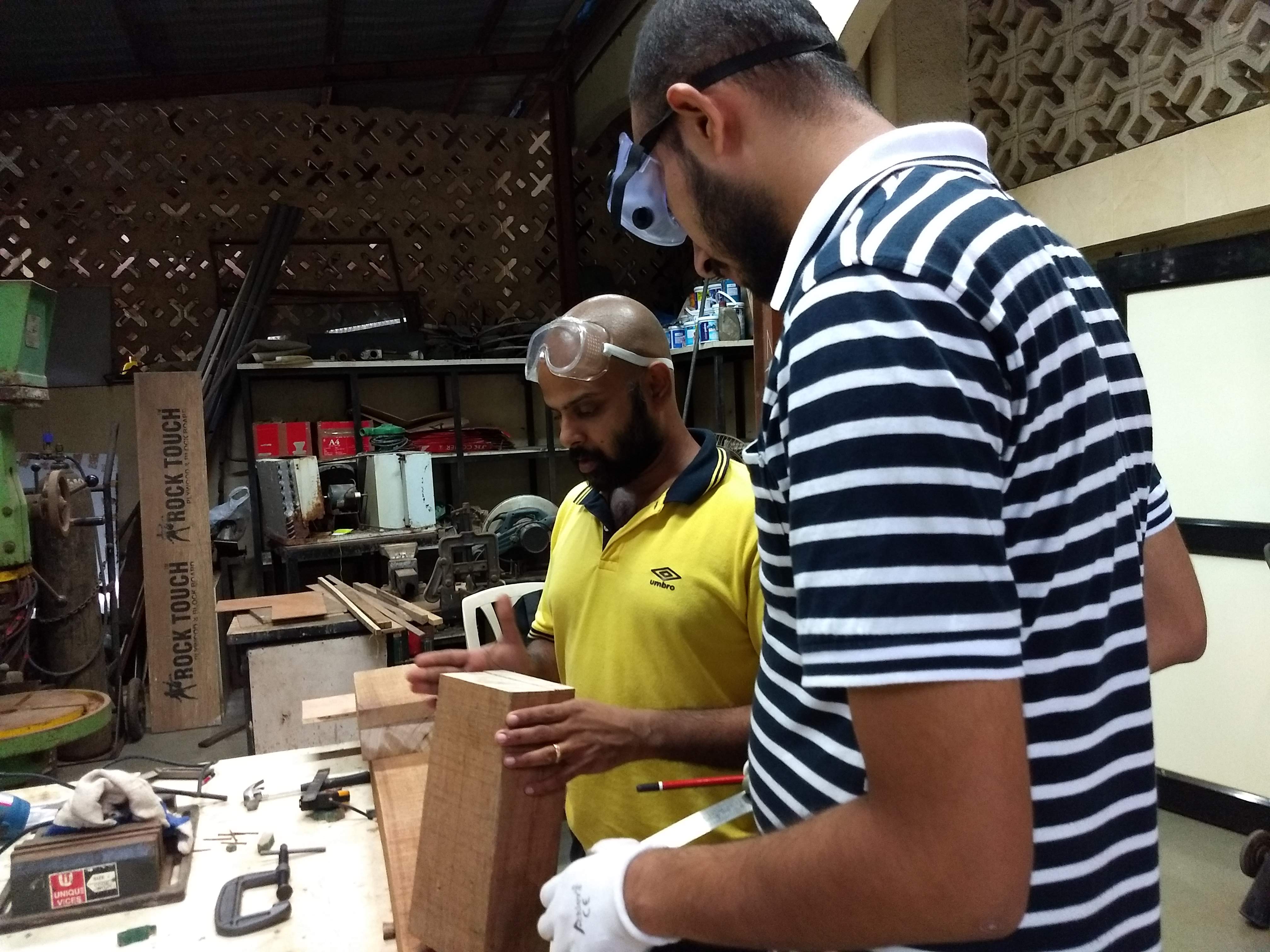
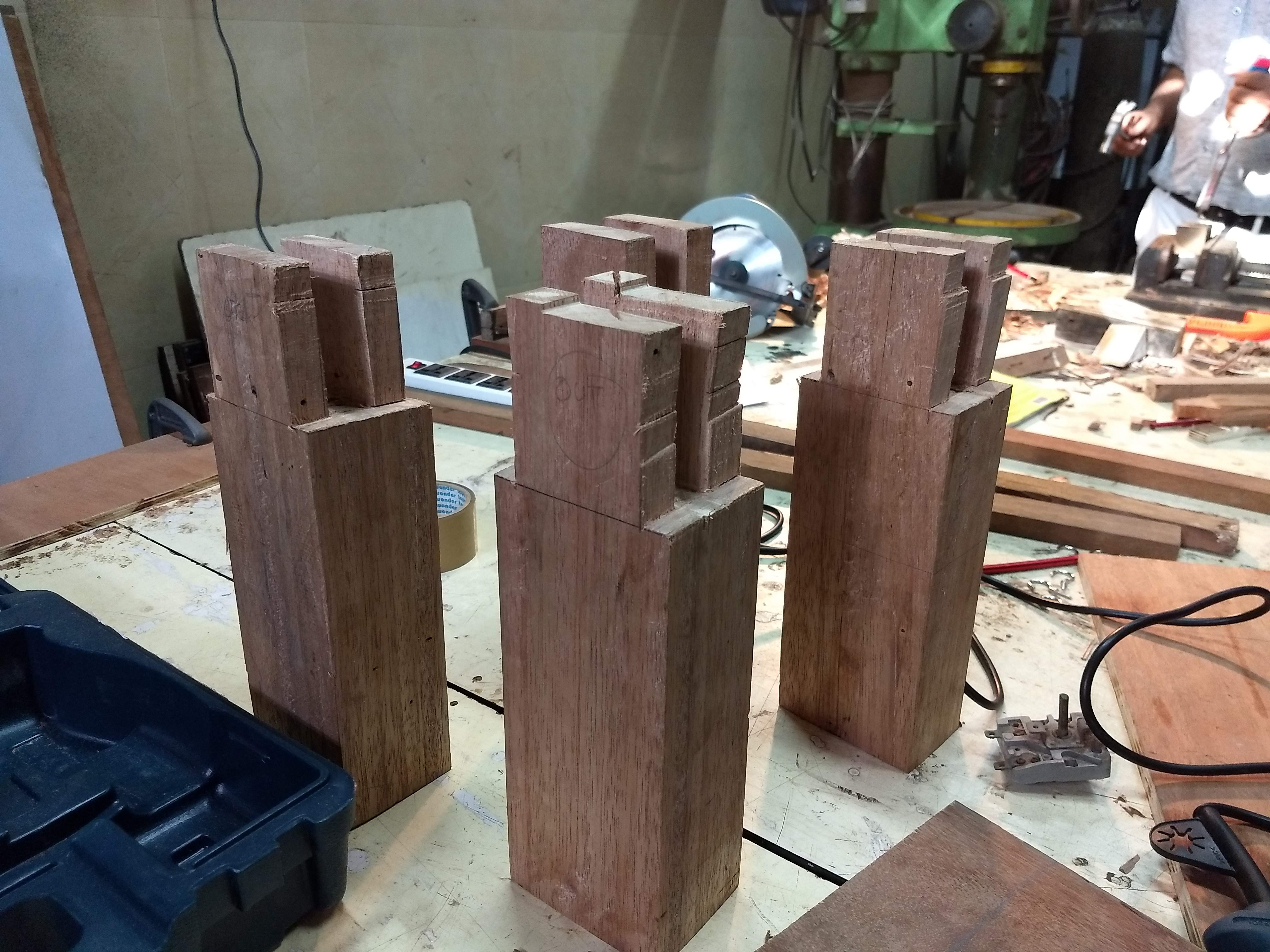
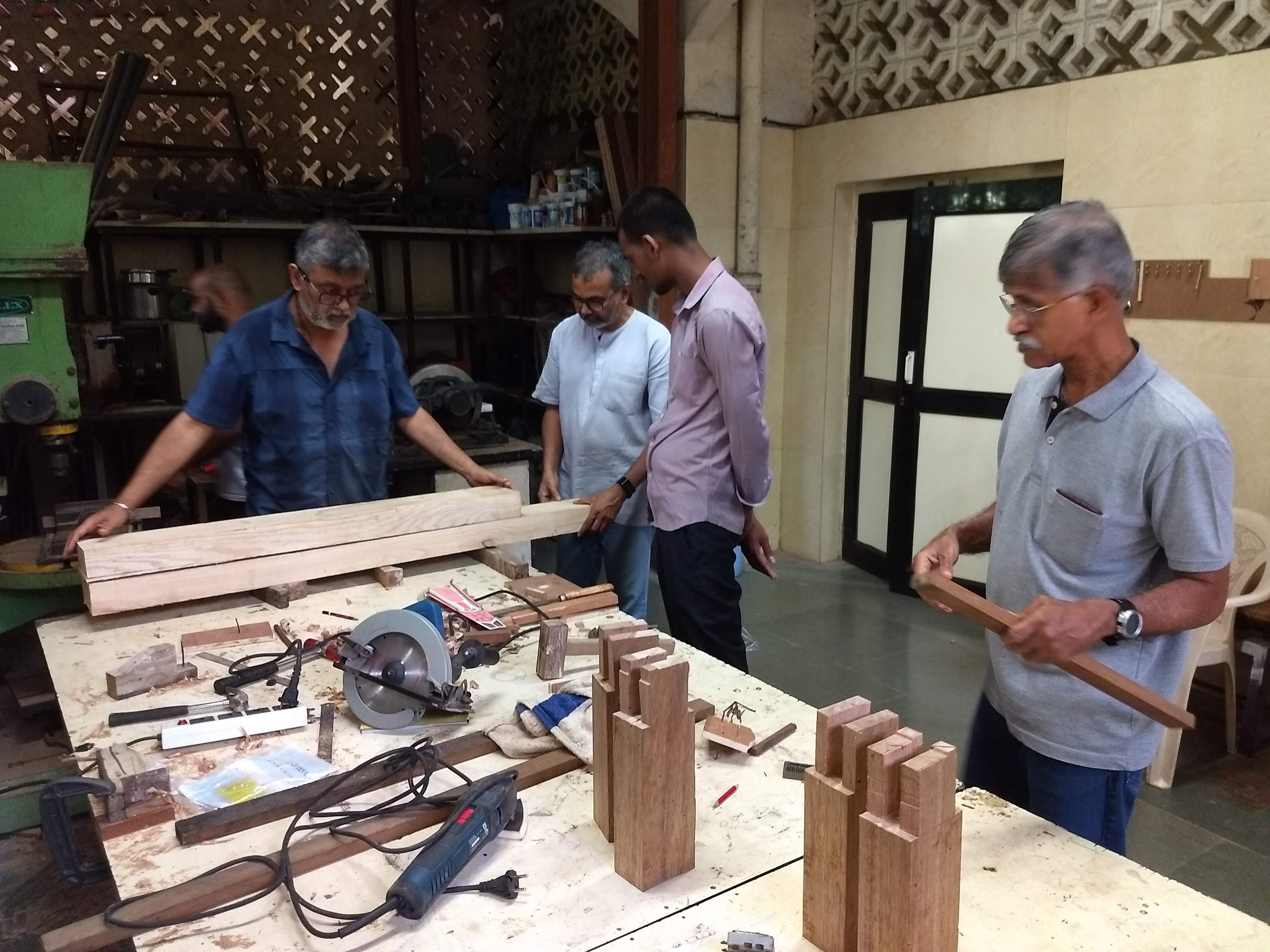
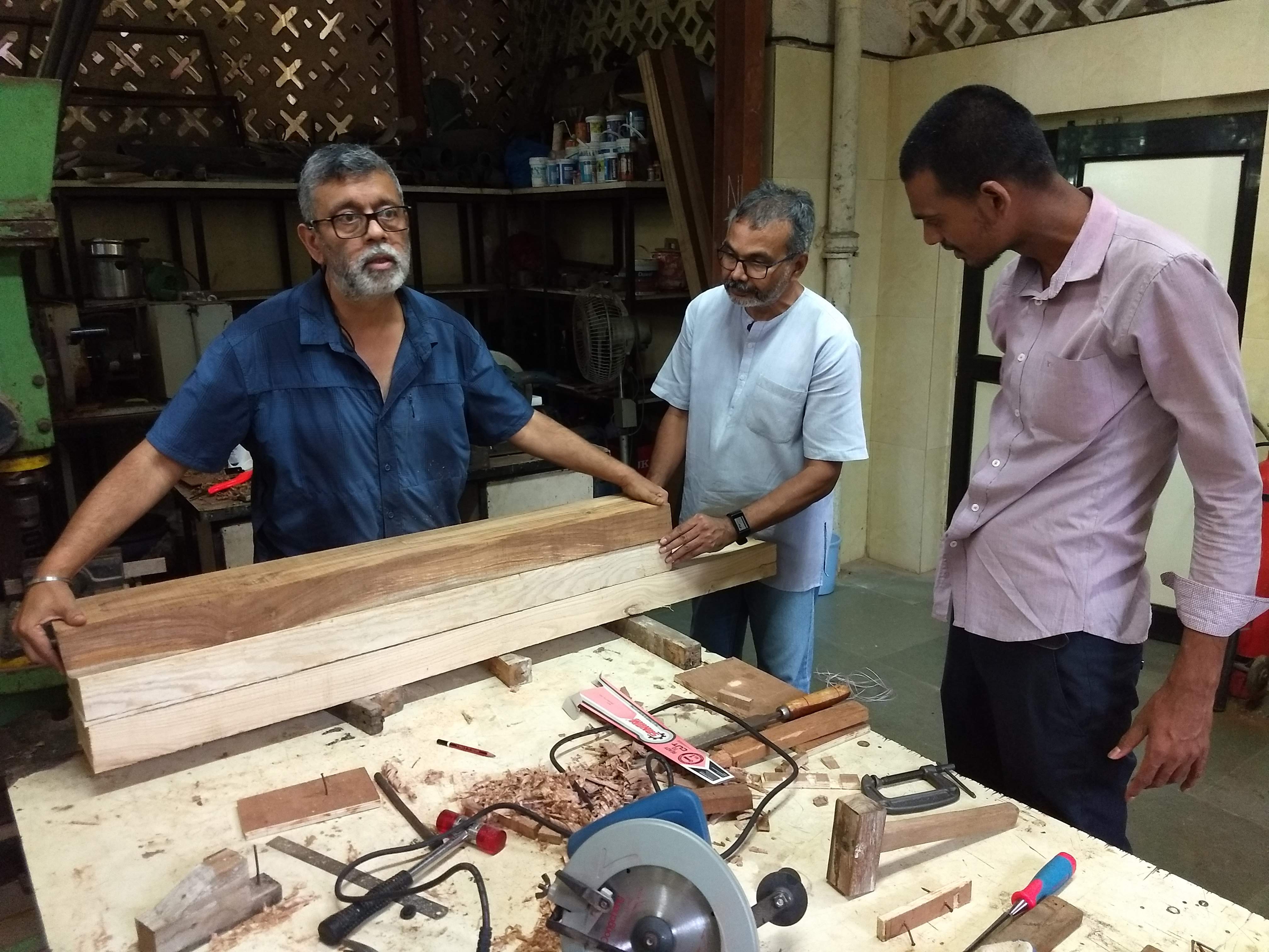
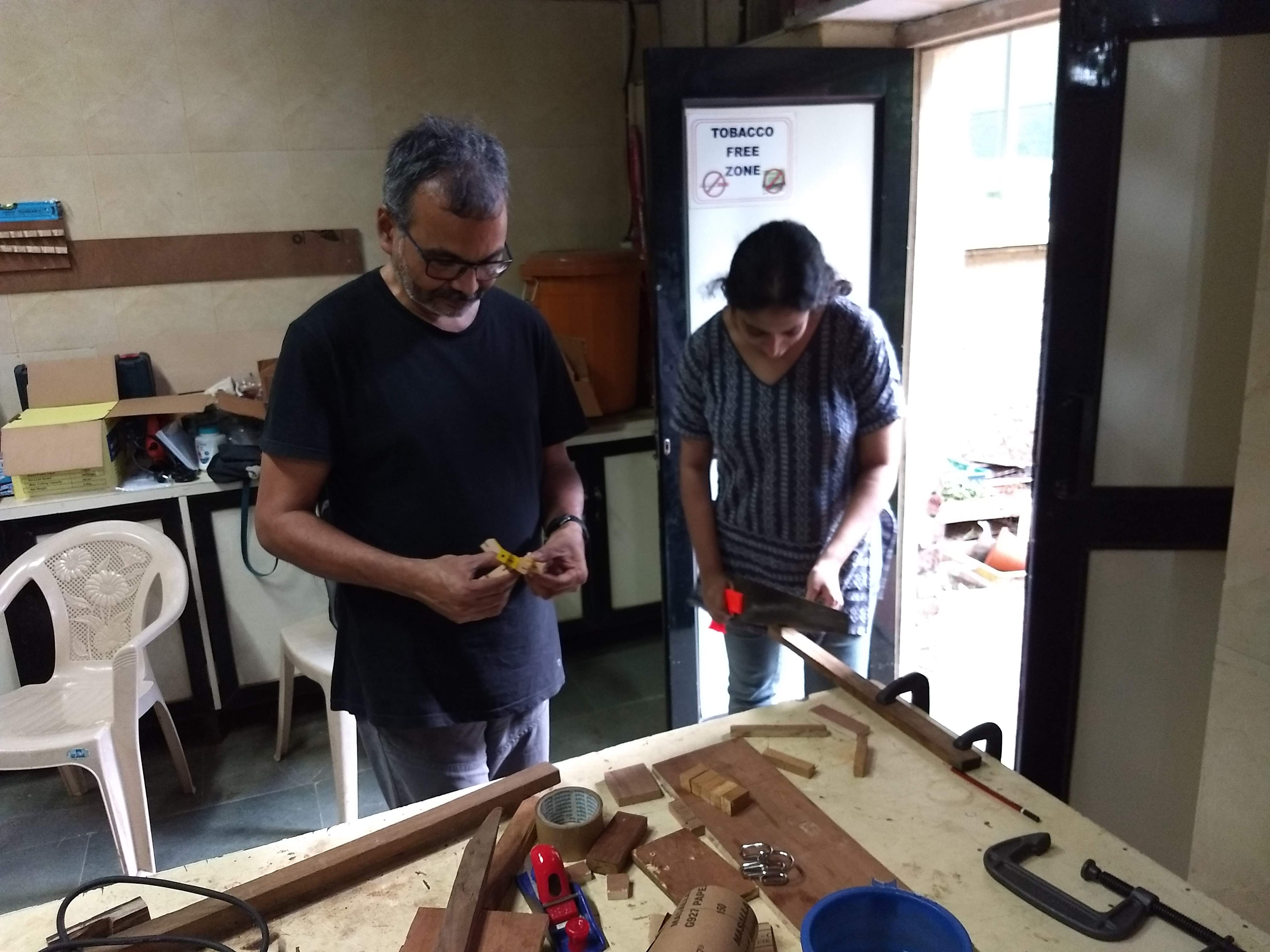
So, finally 4 legs are ready at the end of the day. @Ashish_Pardeshi and @gnowgi@VirenVaz went to buy planer ( ranga) from the nearby shop. @jtd , @Puneet are @ravitoys31 are brainstorming on the dimension of the table.
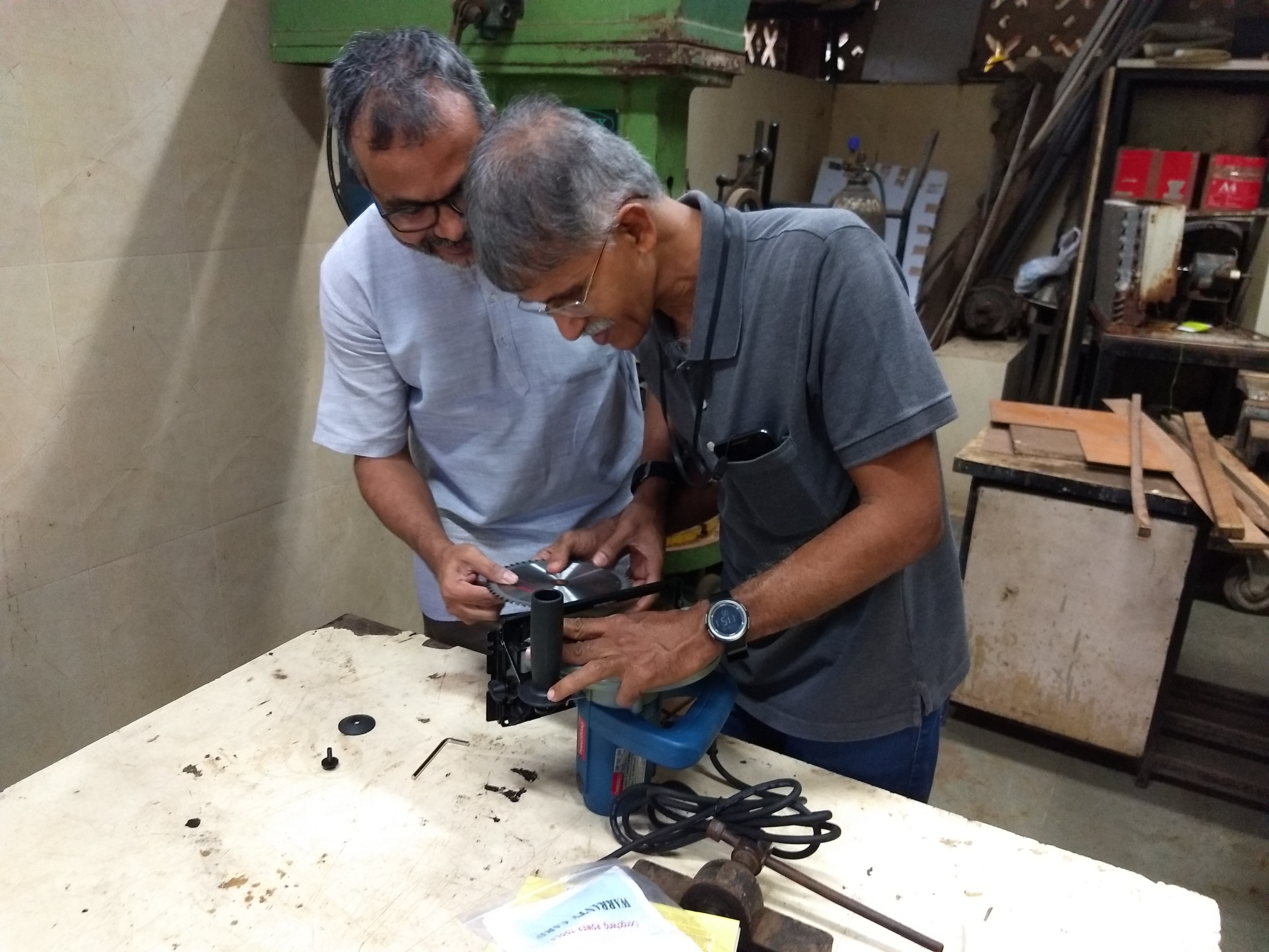
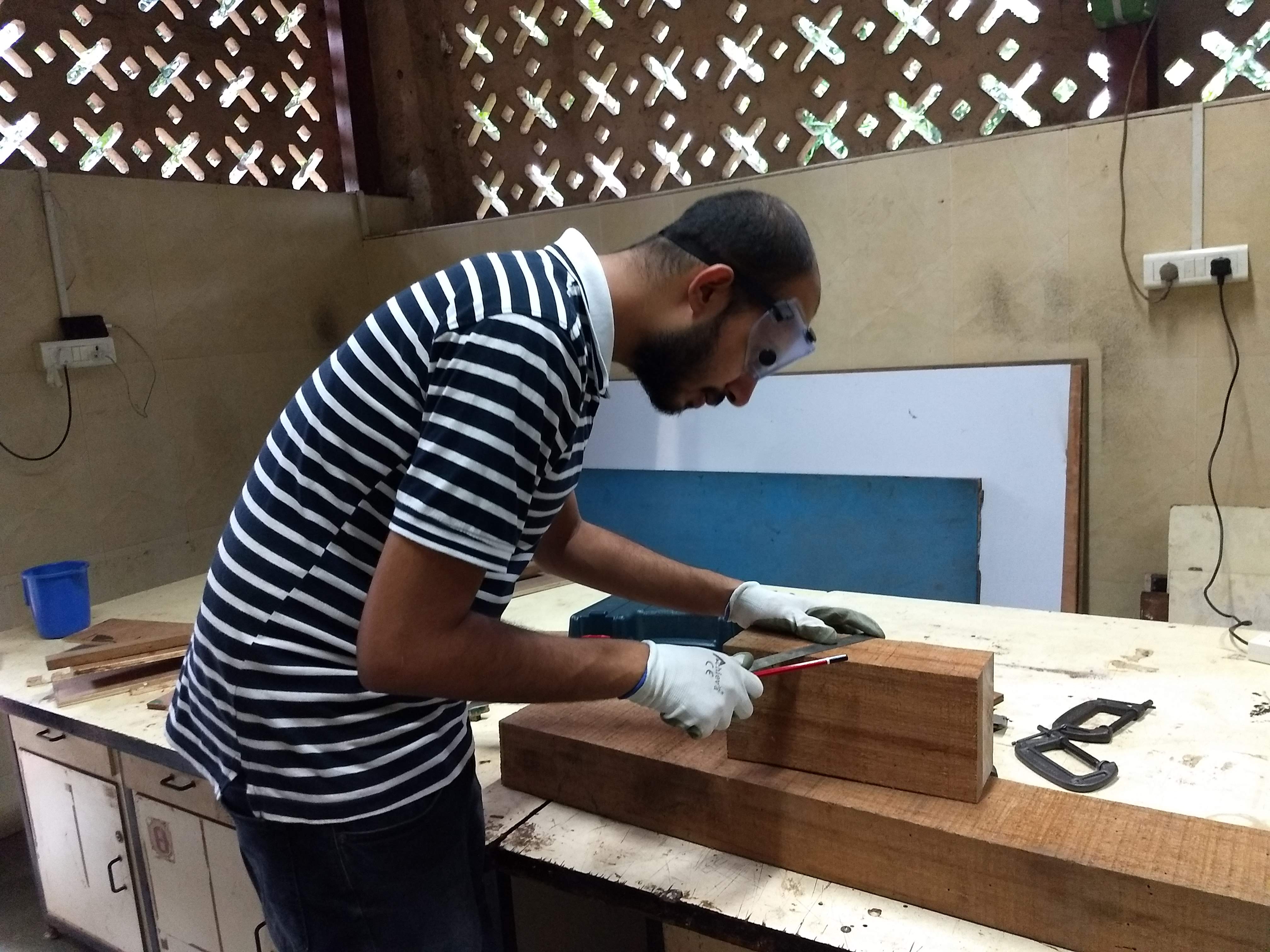
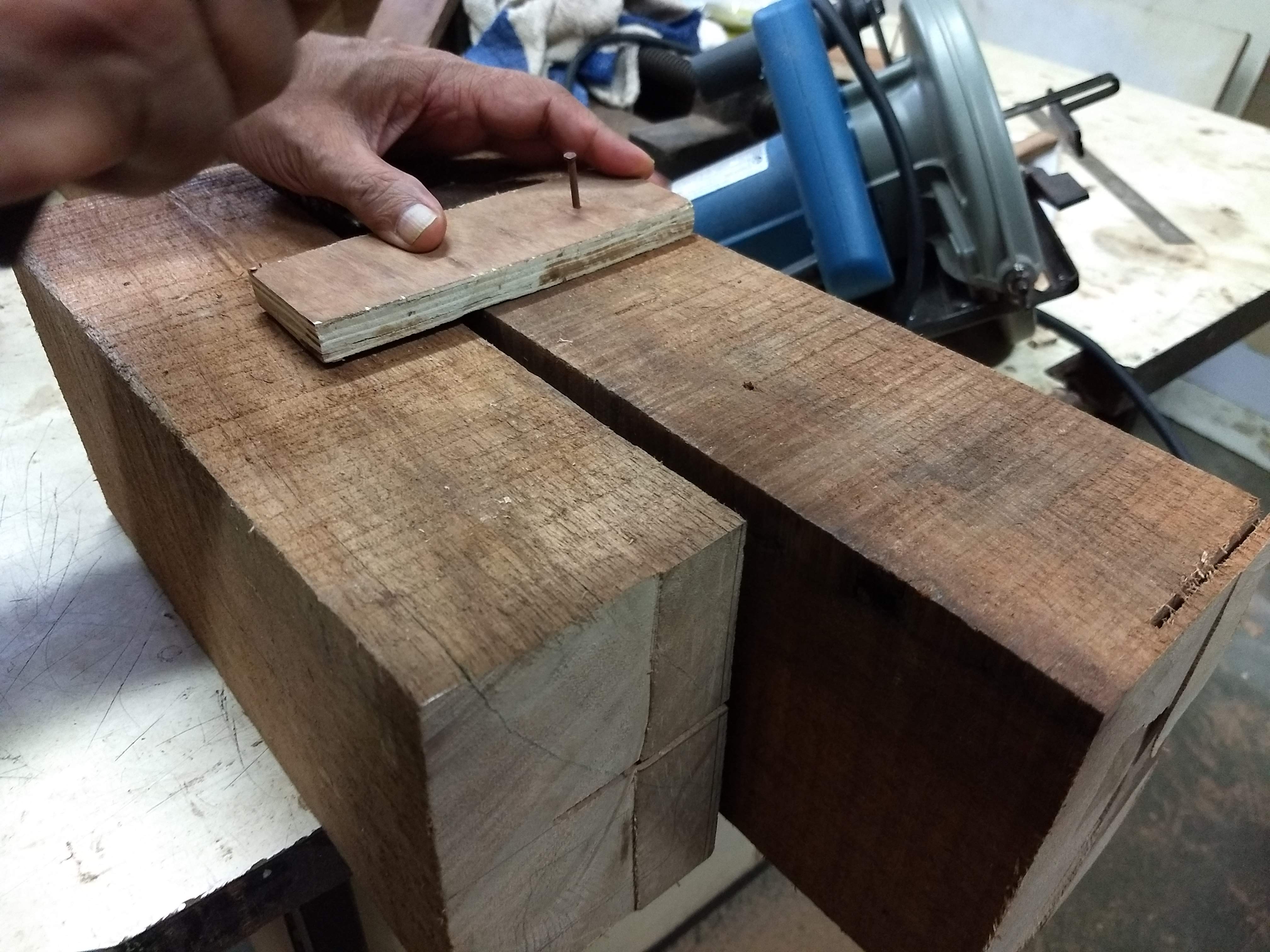
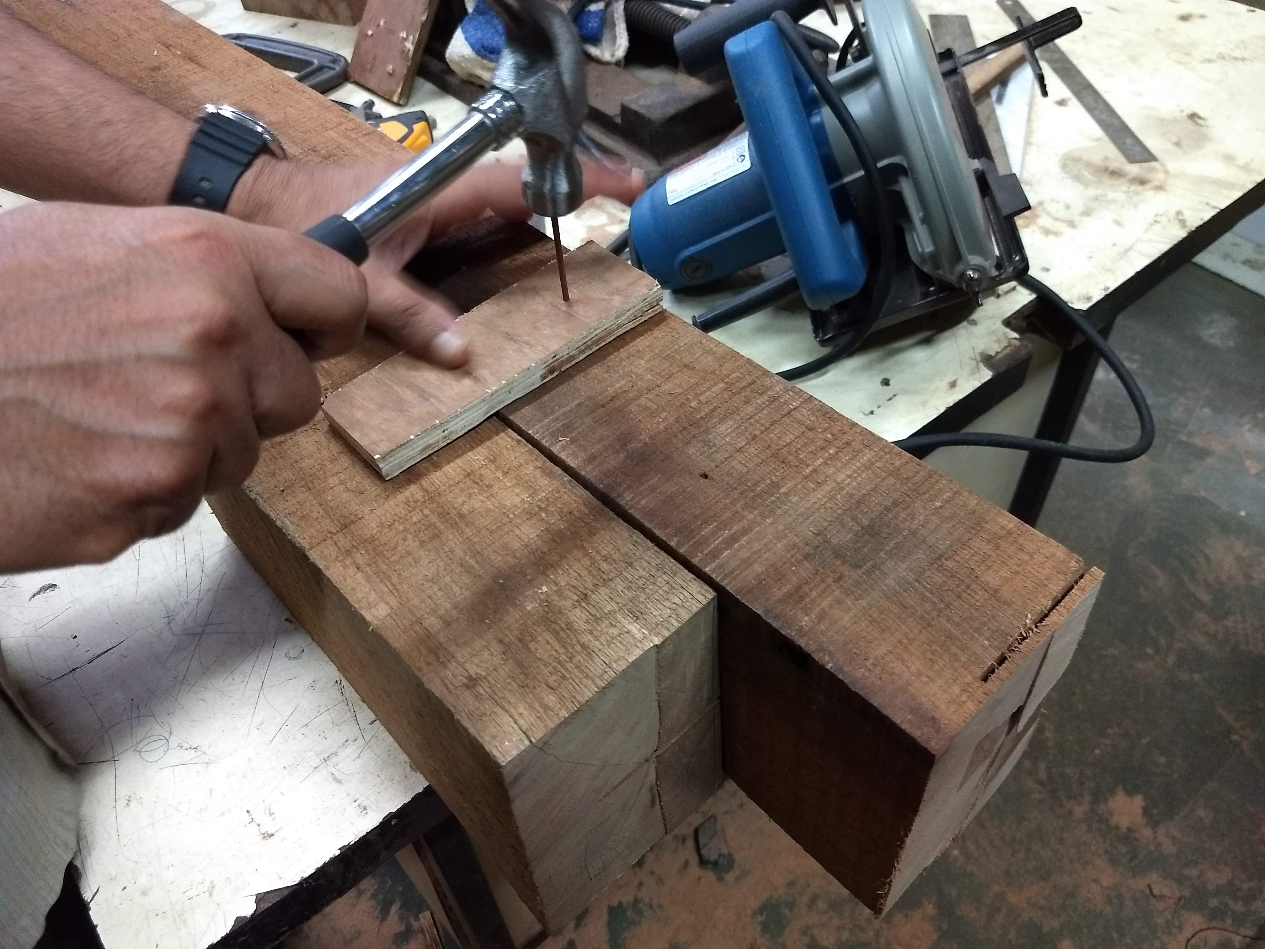
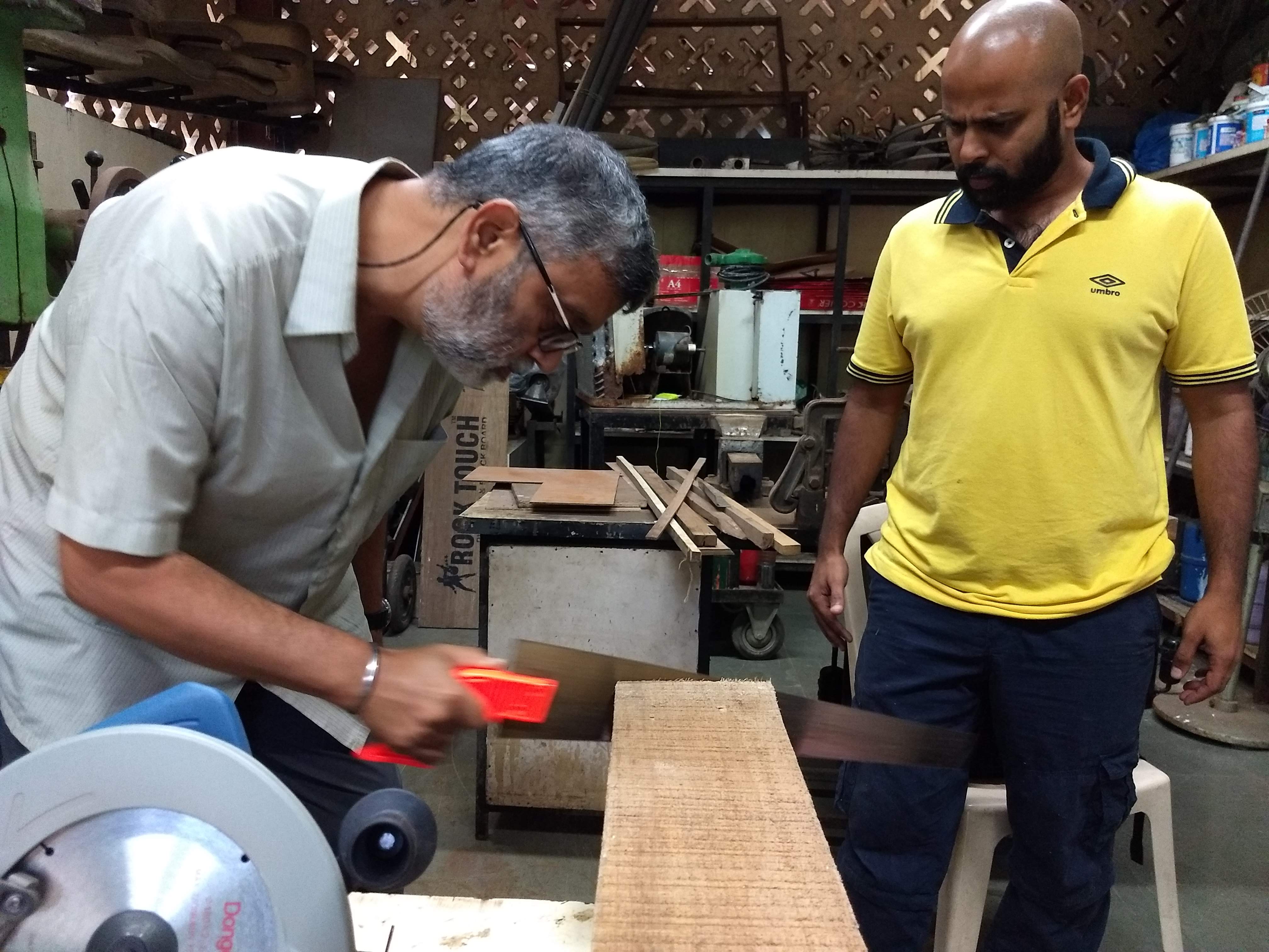
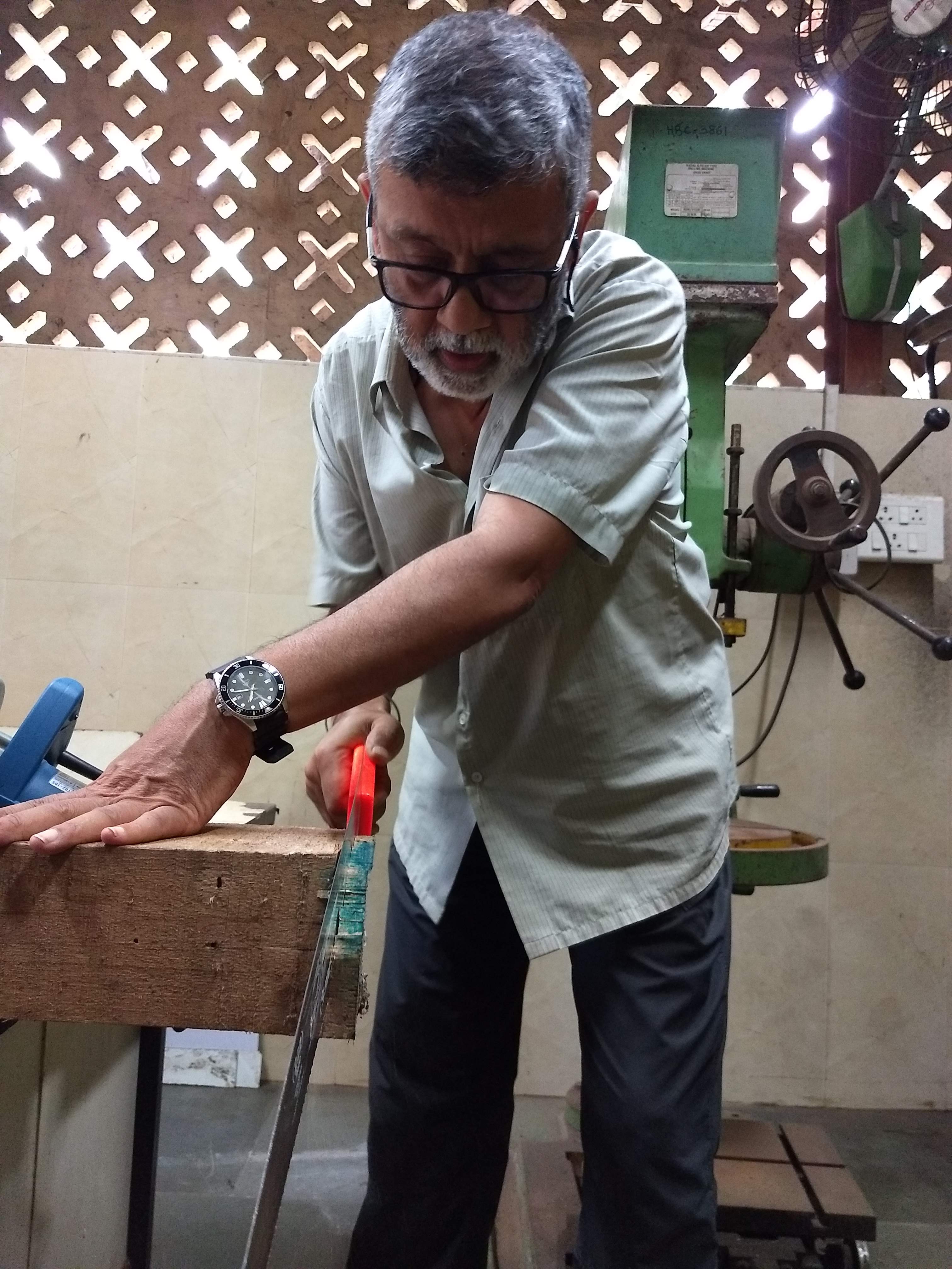
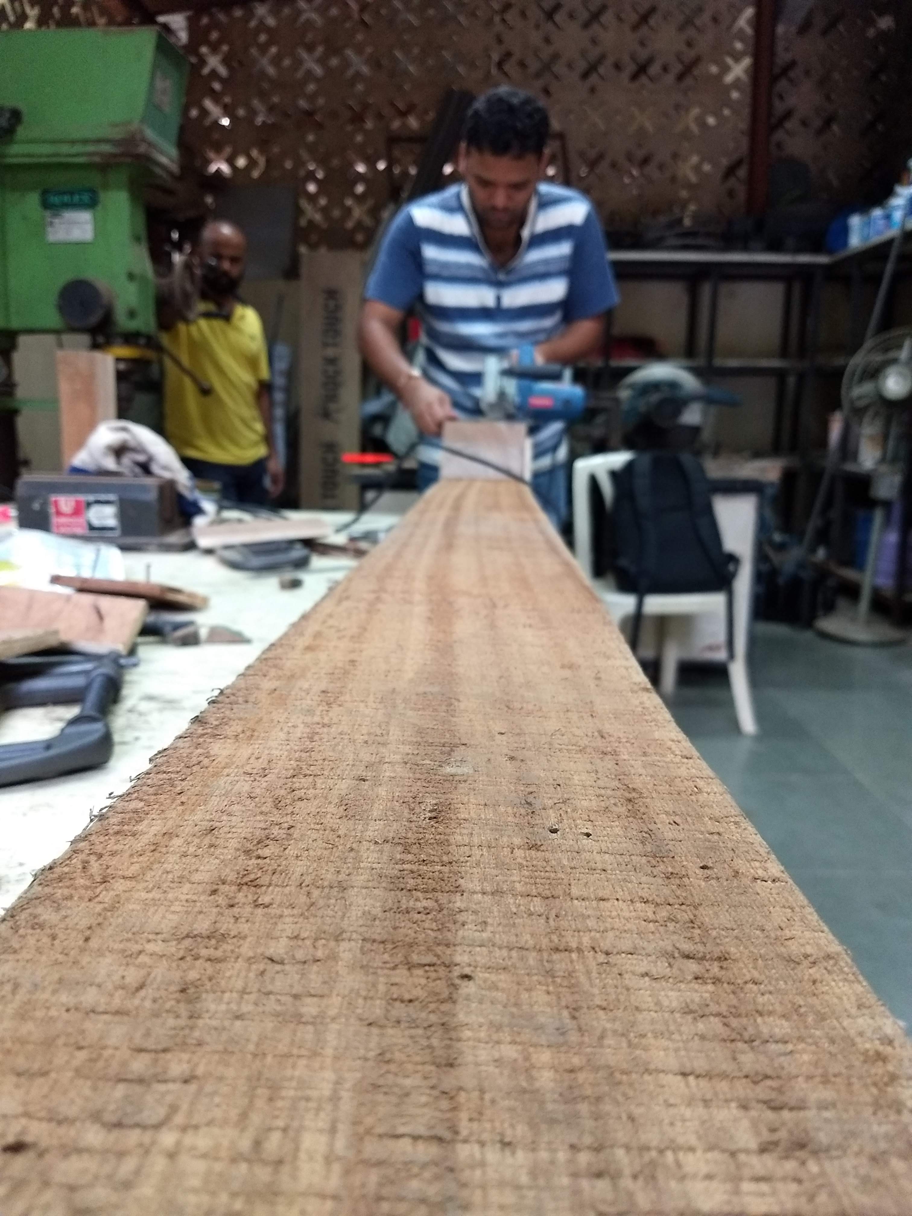
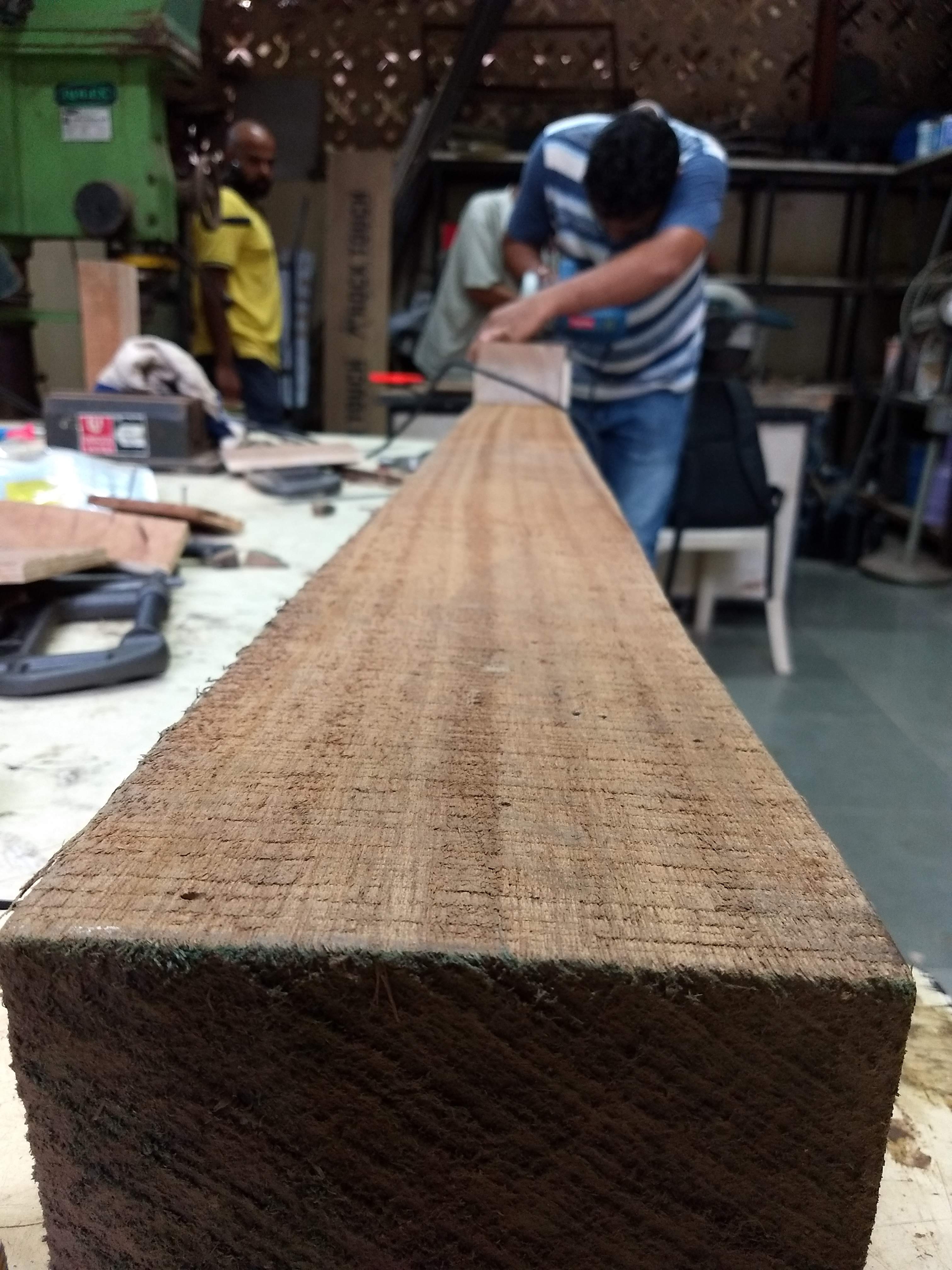
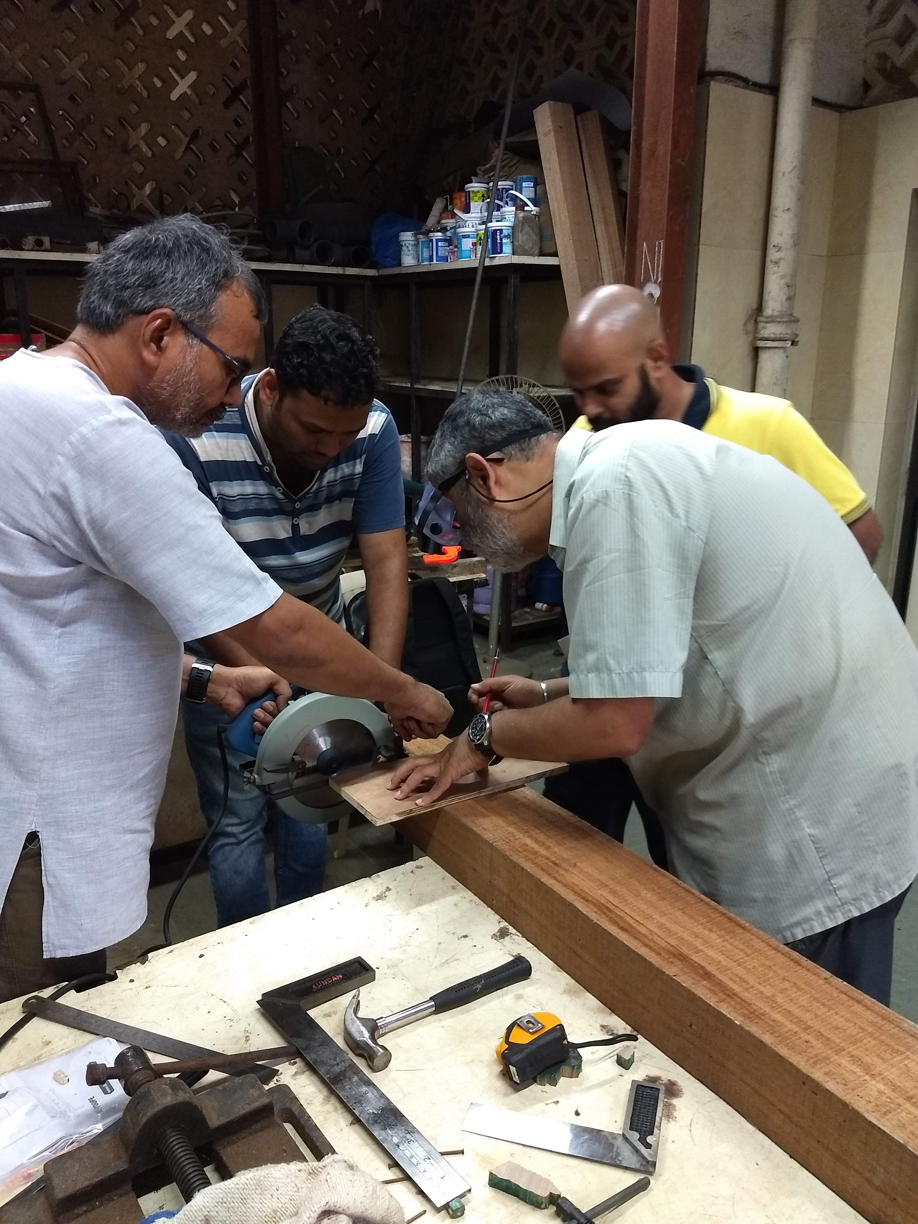
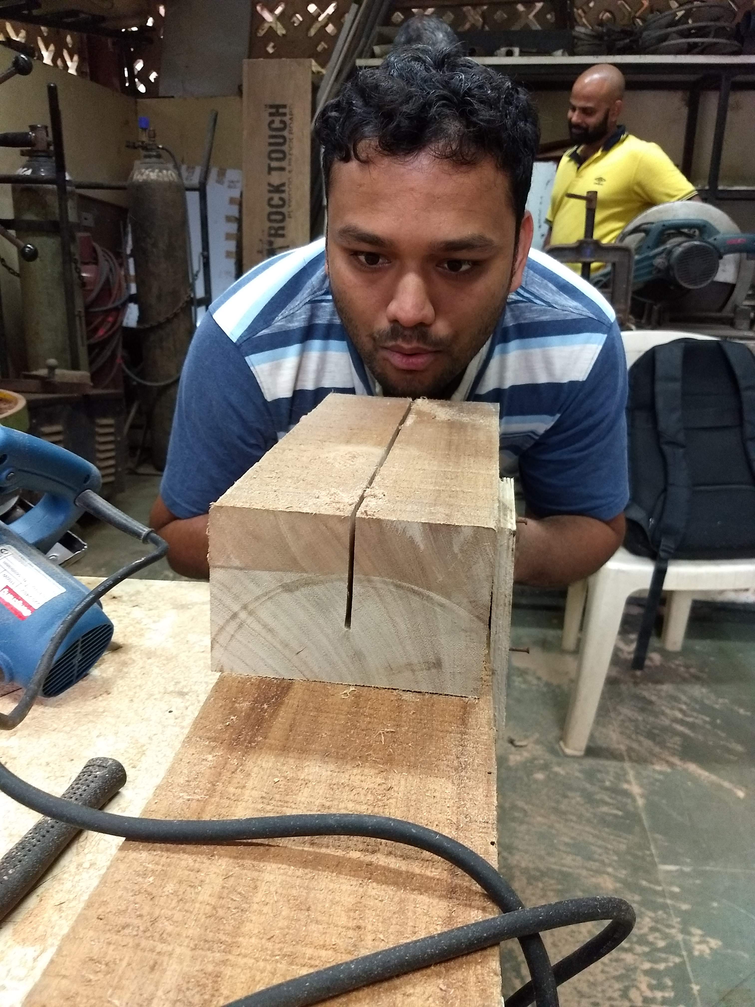
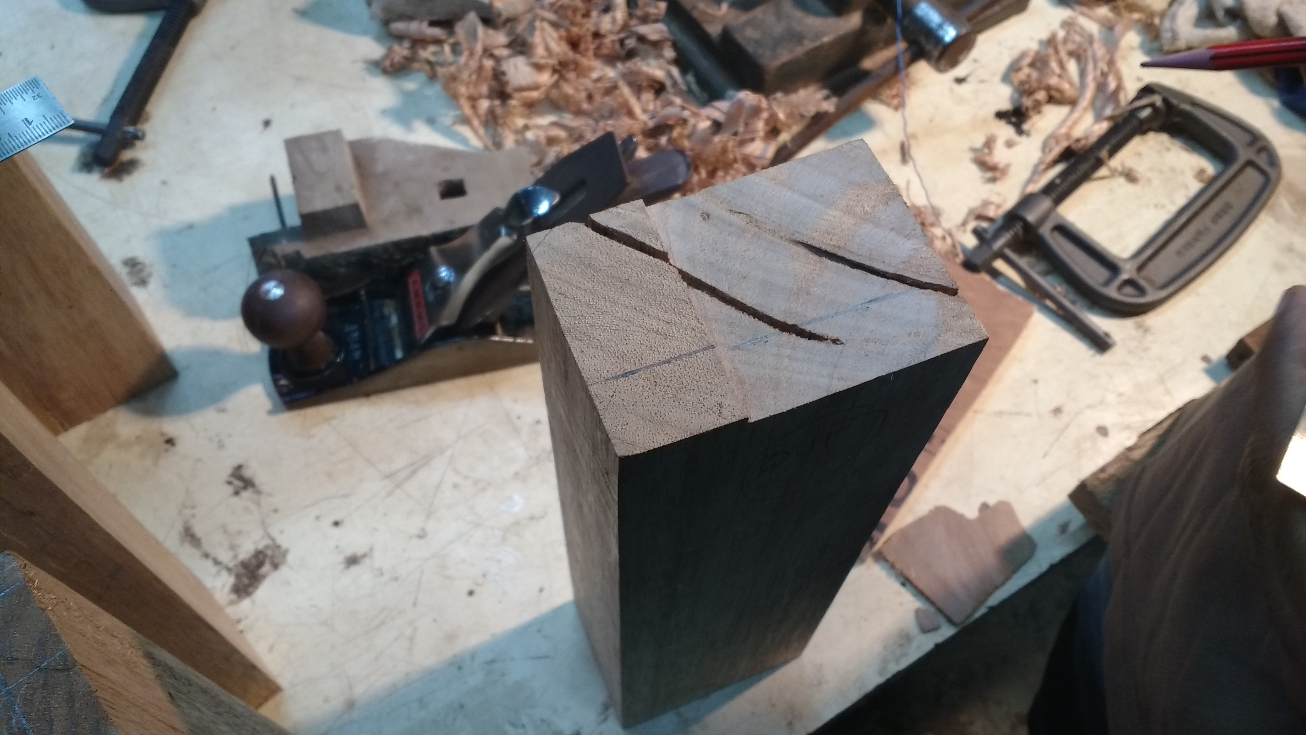
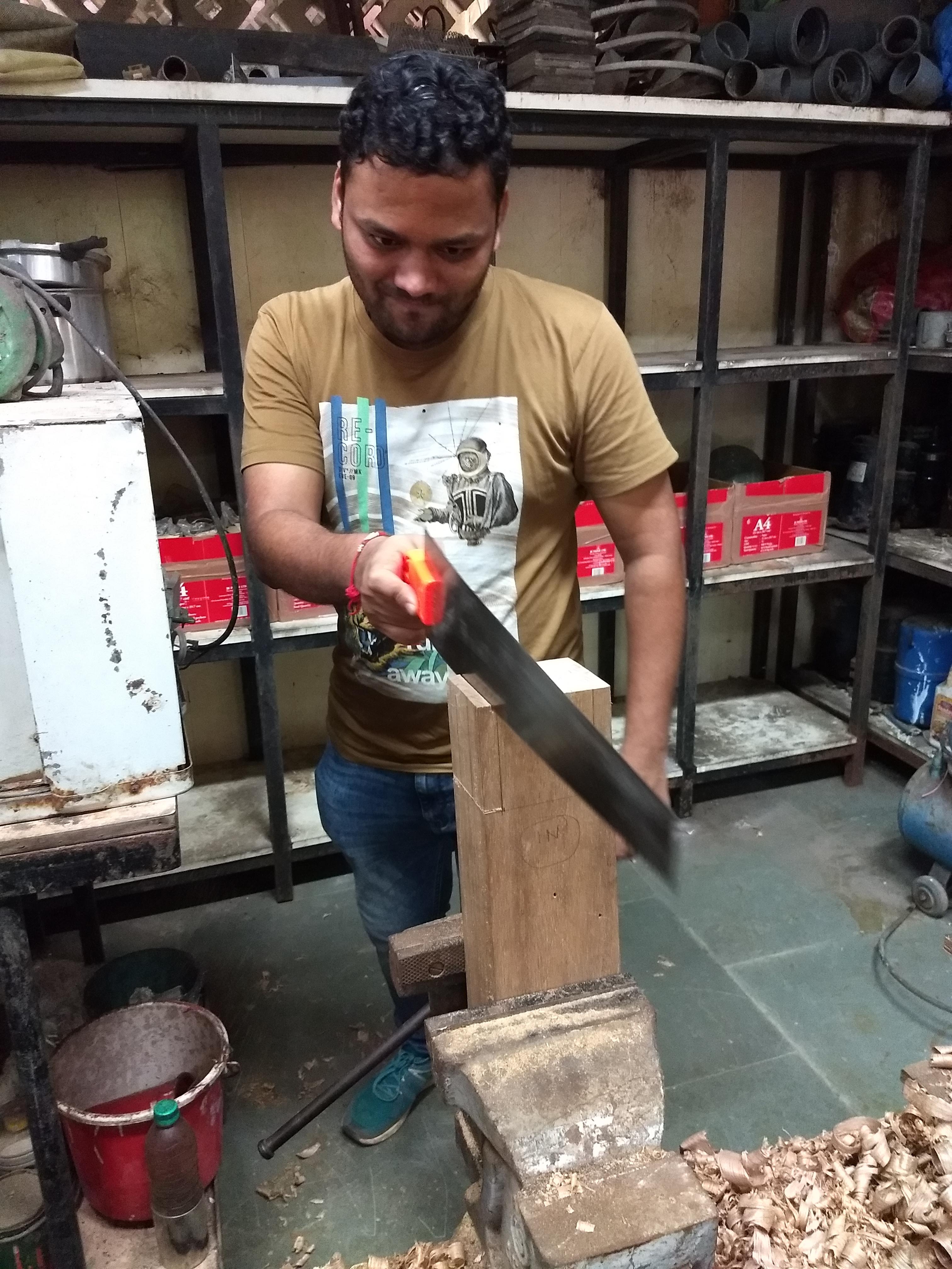
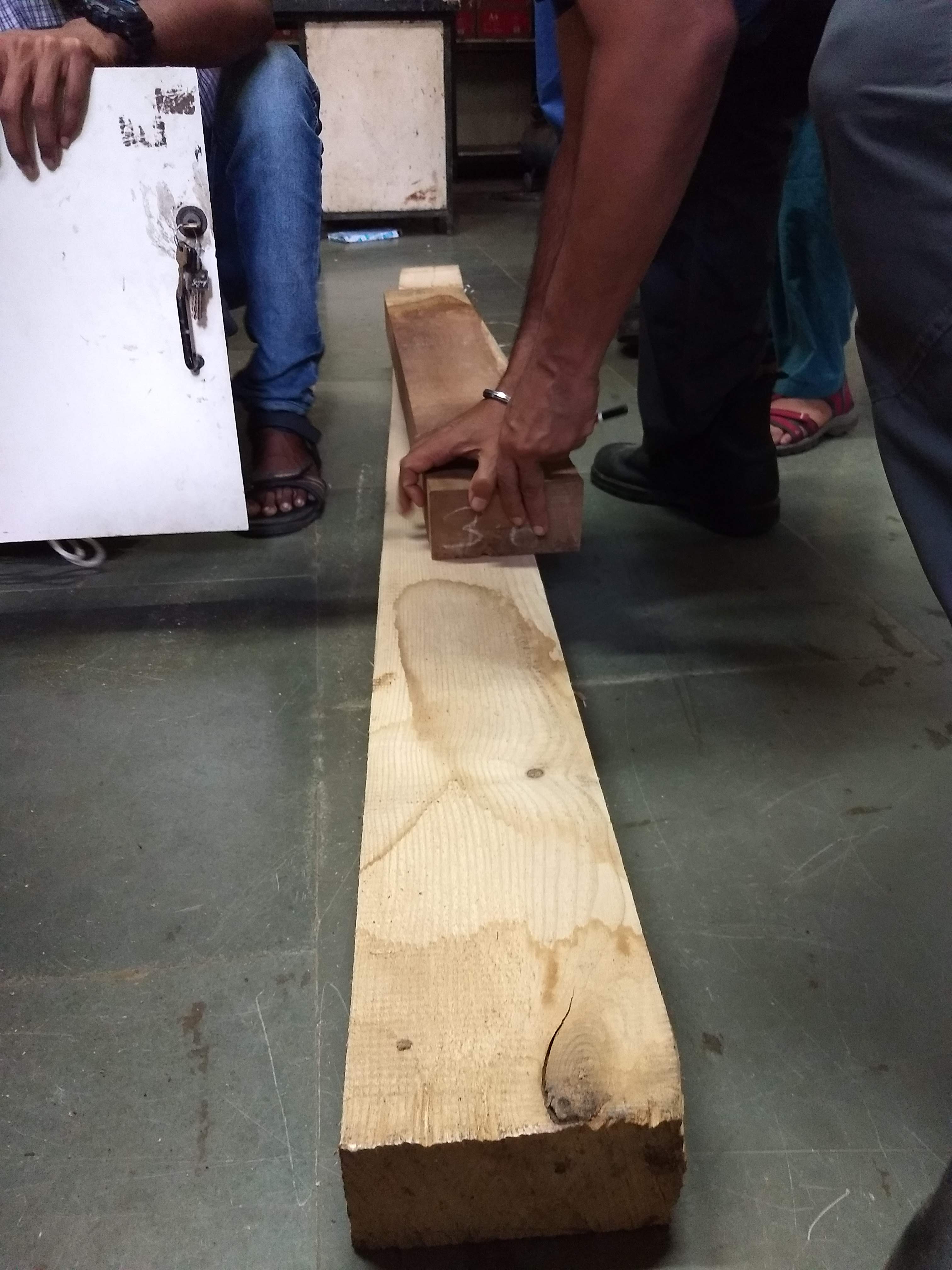
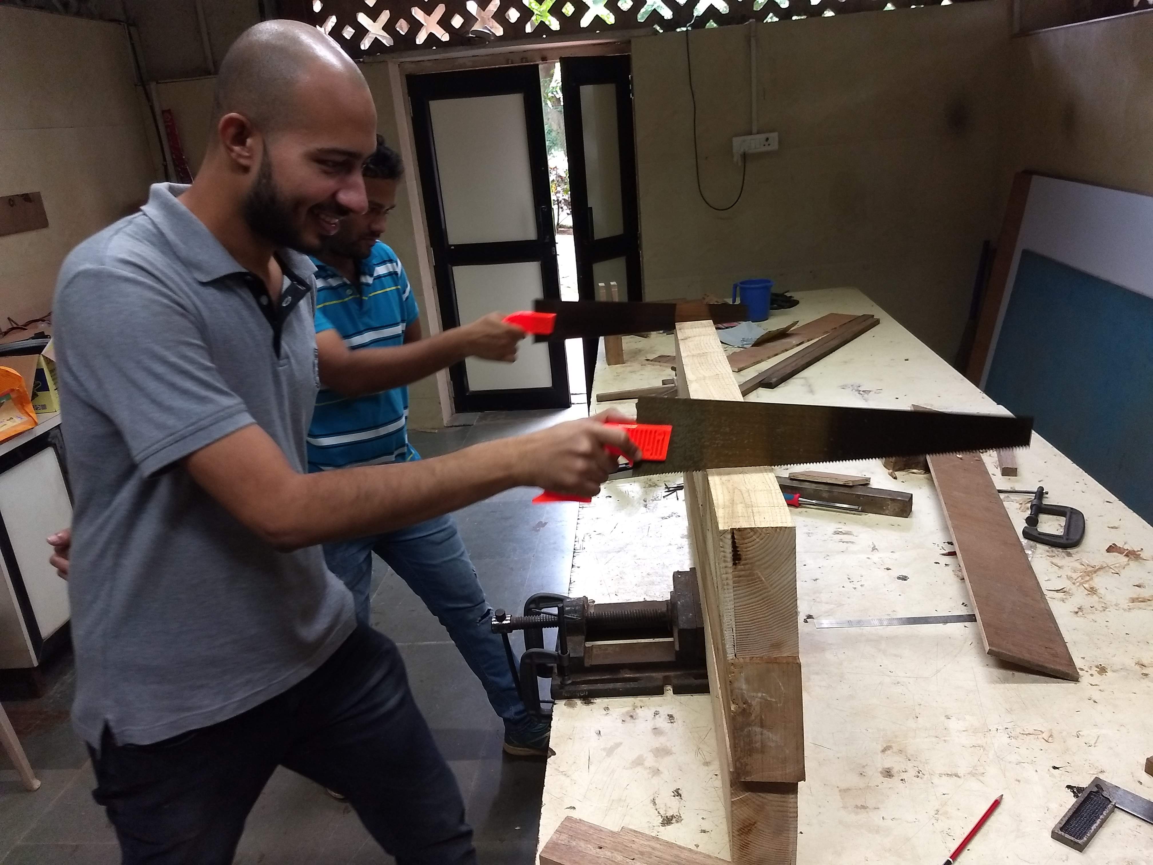
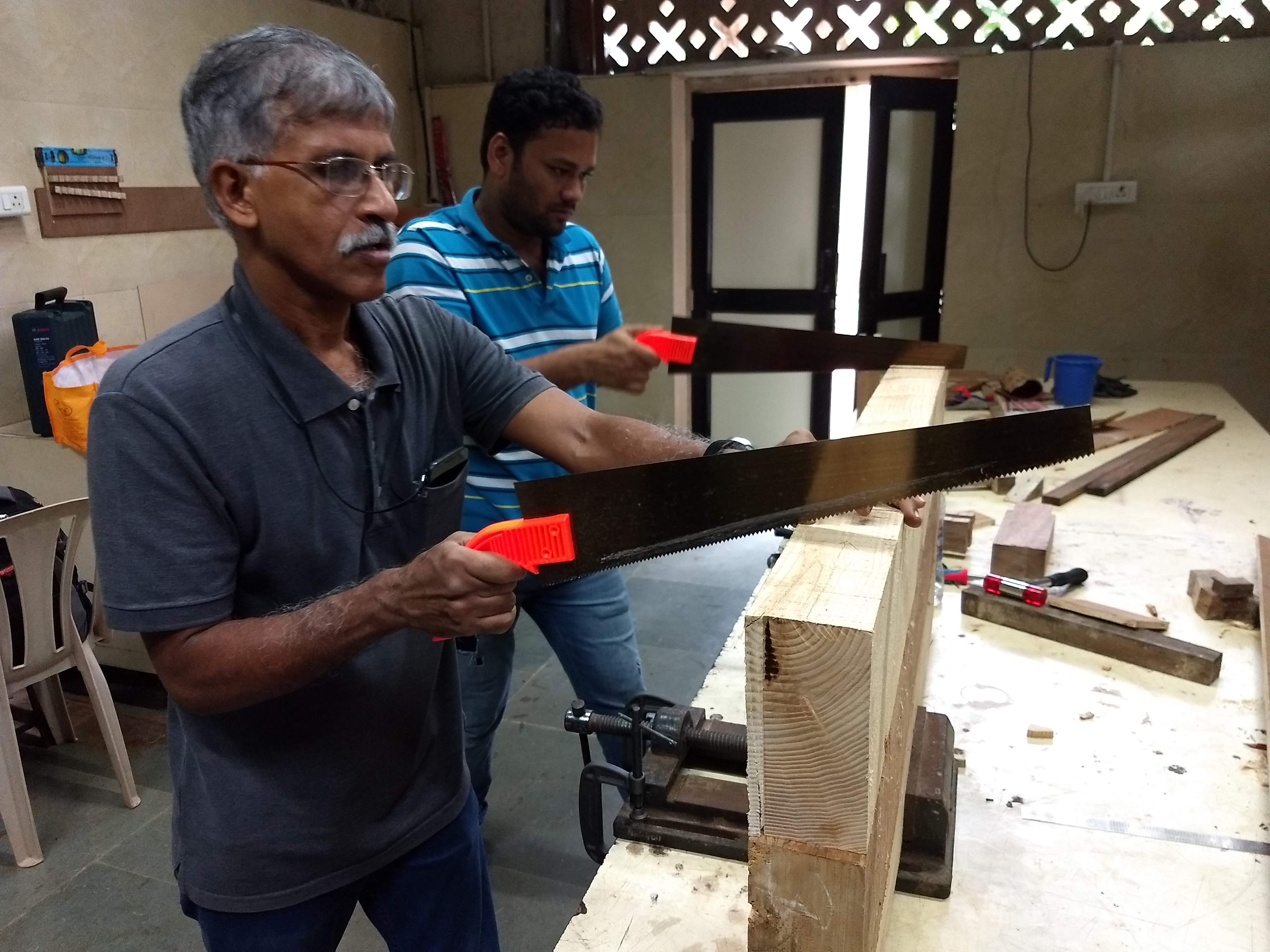
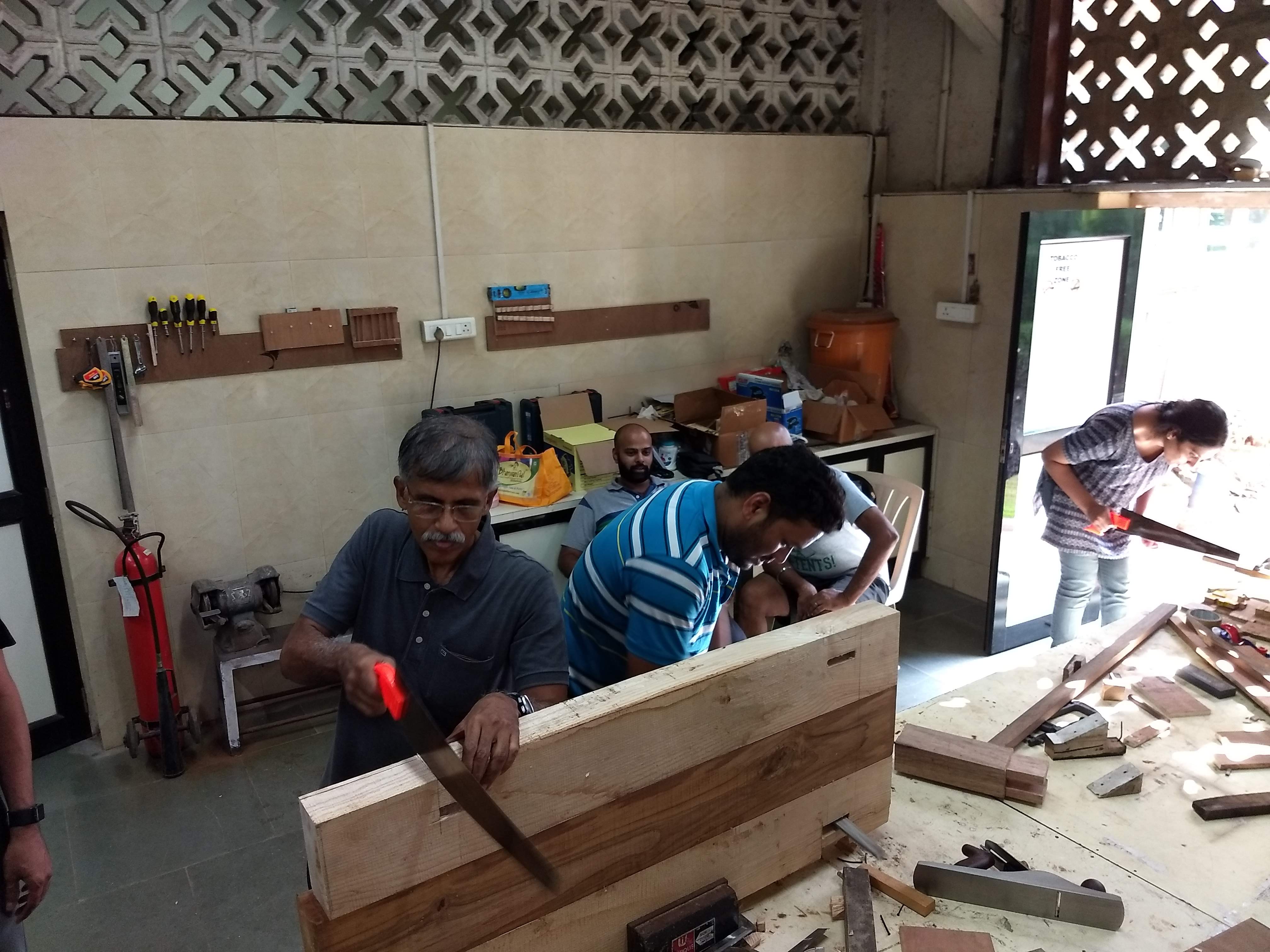
We learned a couple of neat tricks from @VirenVaz how to use circular saw to split a thick wooden of around 1 ft if you don’t have a clamp! We used nail and plywood pieces to hold the smaller wooden piece with the larger log so that it remains stable and then used the circular saw to cut through it.
After that, if you invert the process and if you have time, you can use the pull saw to slowing slice through the remaining portion or repeat the same process and cut using the electric circular. The depth to which the circular saw is able is cut is around 2.5 inch.
Here are the glimpses of the various attempts:
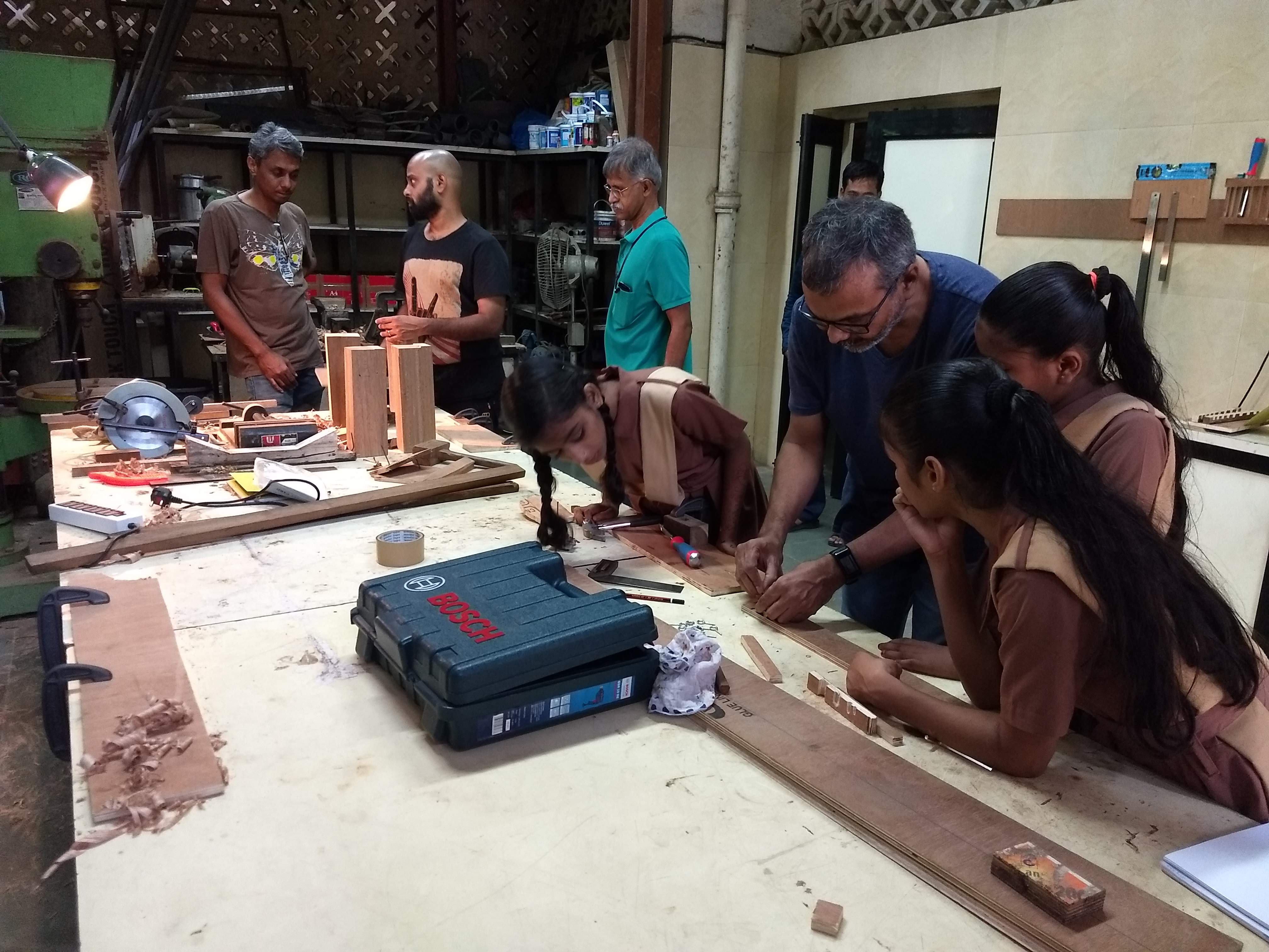
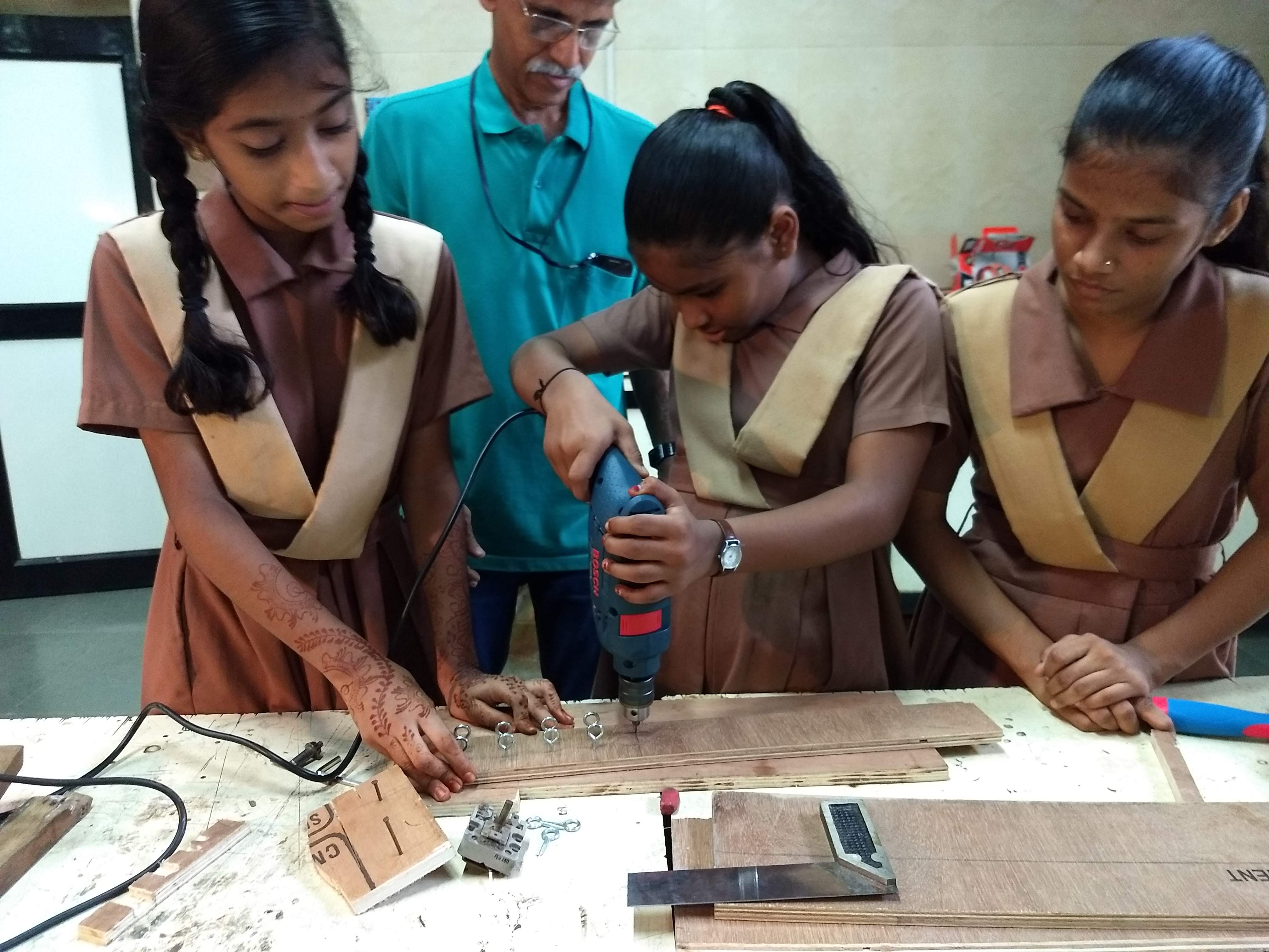
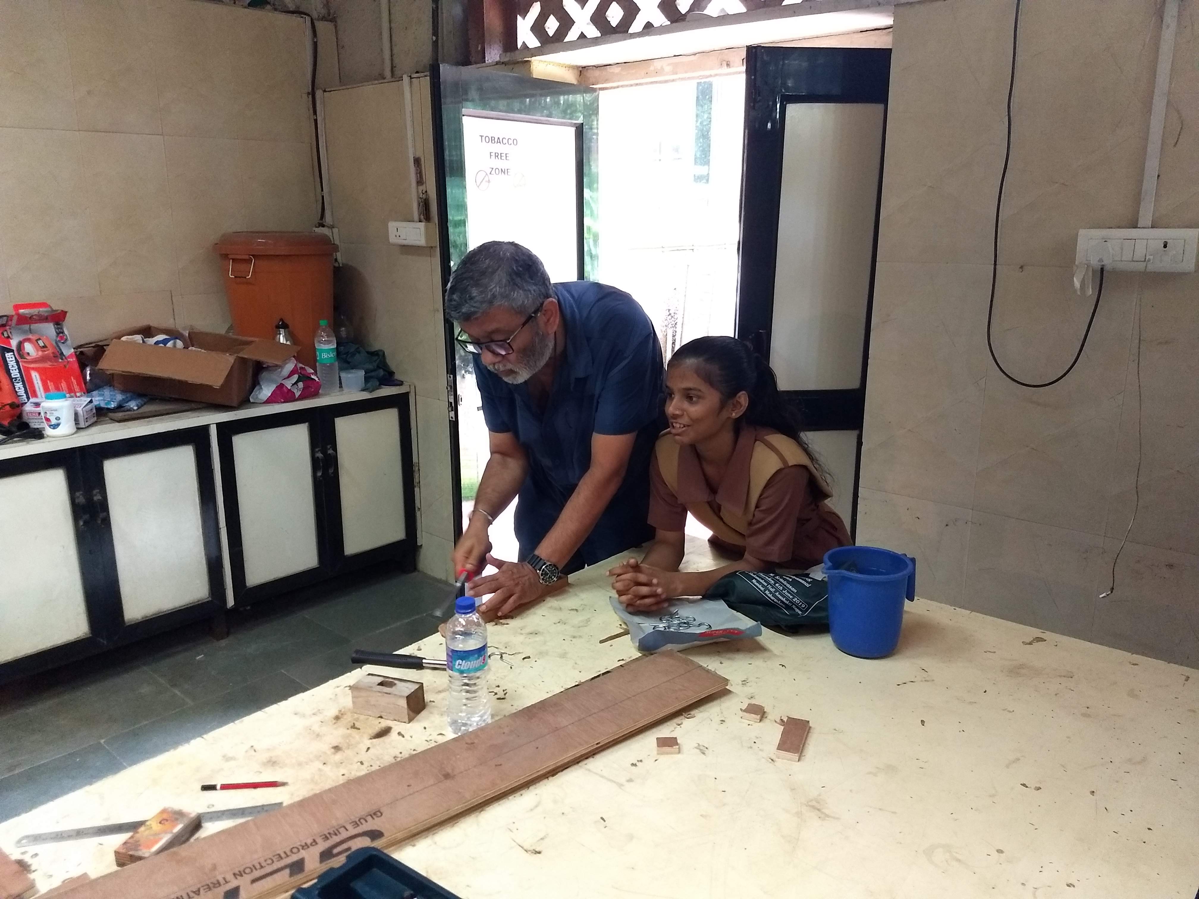
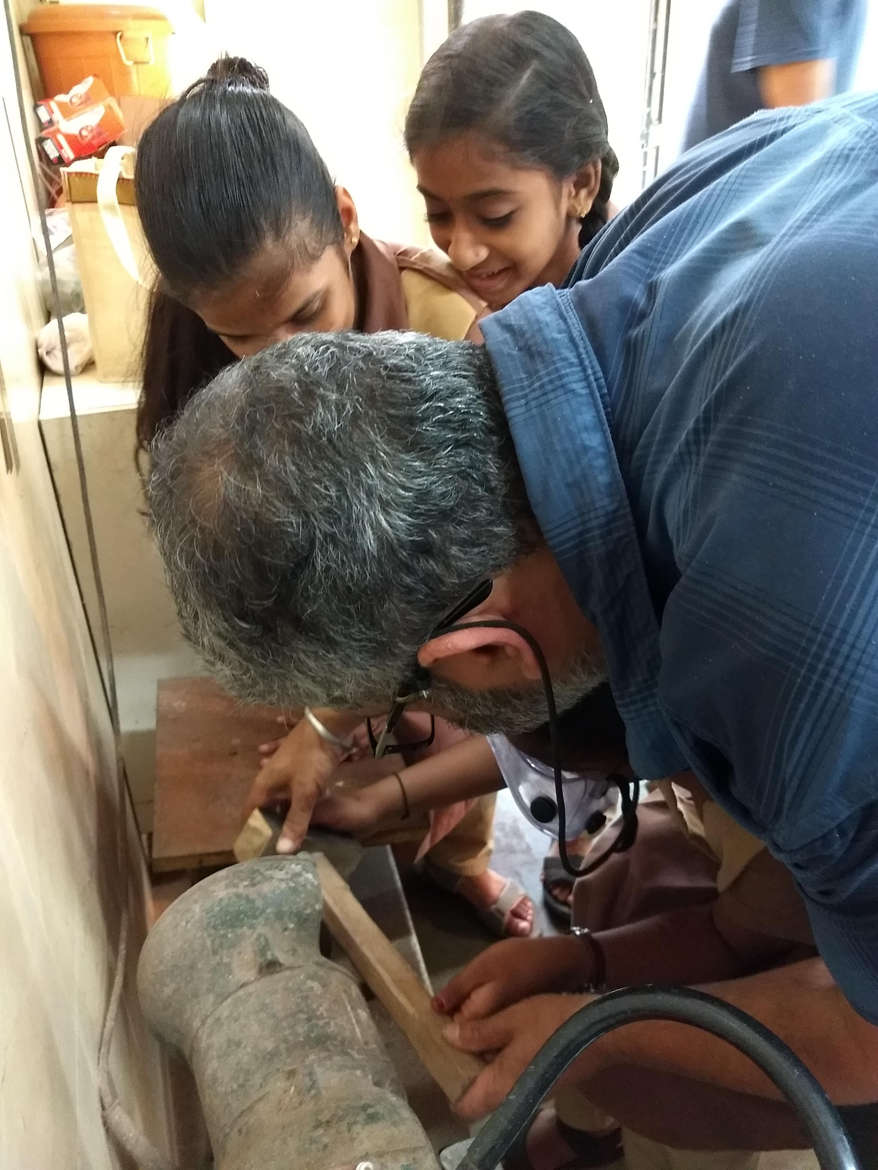
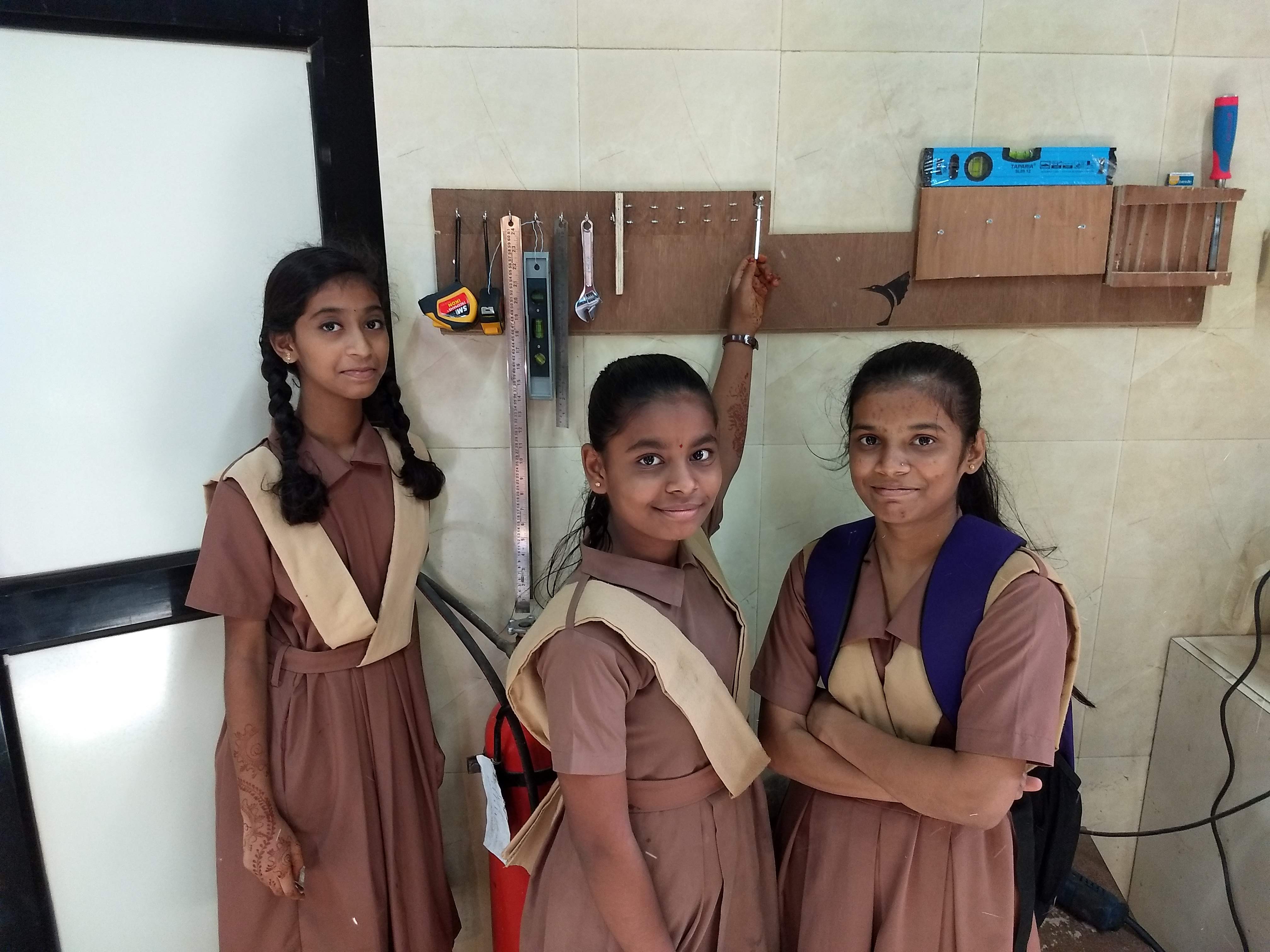
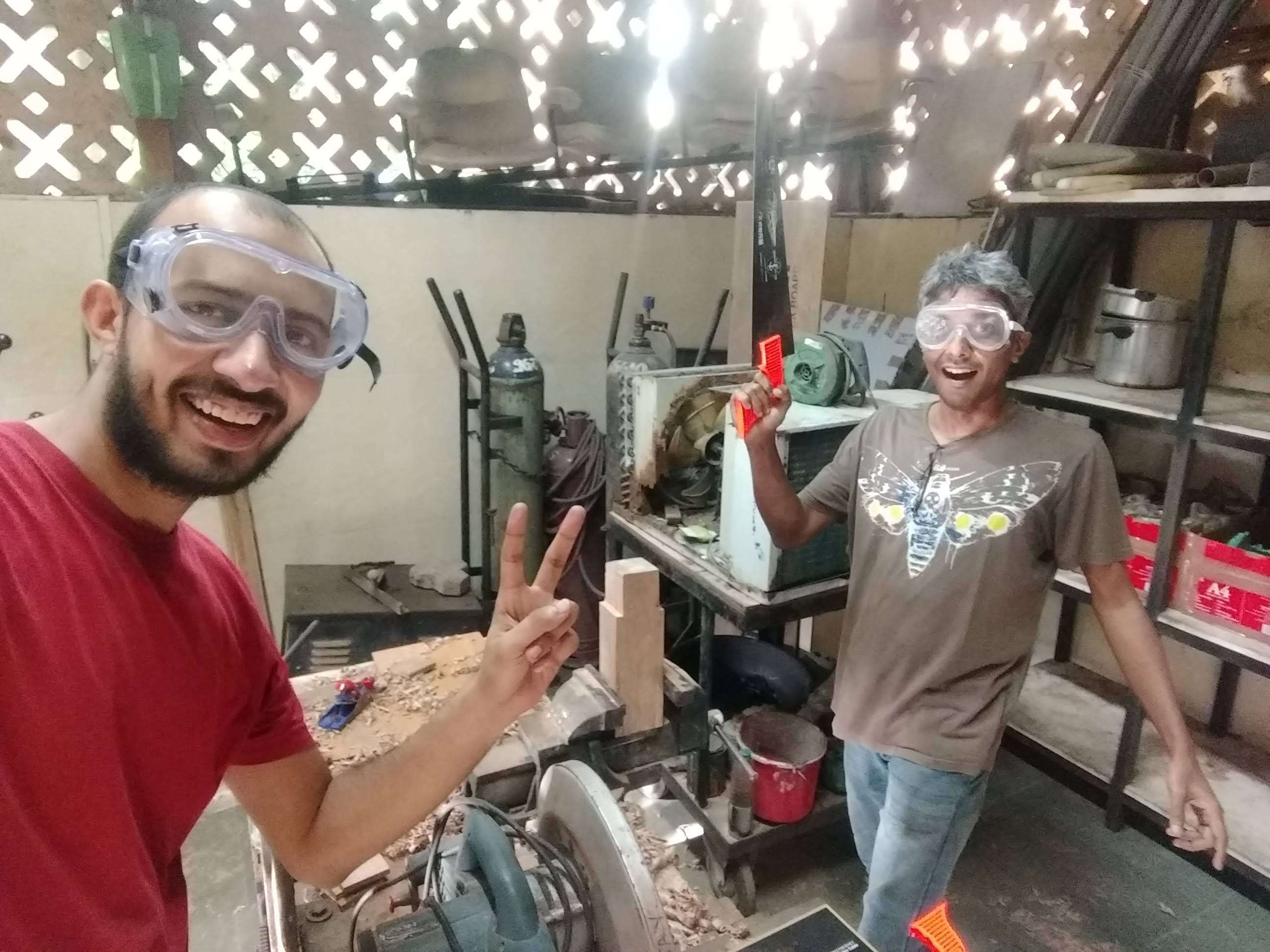
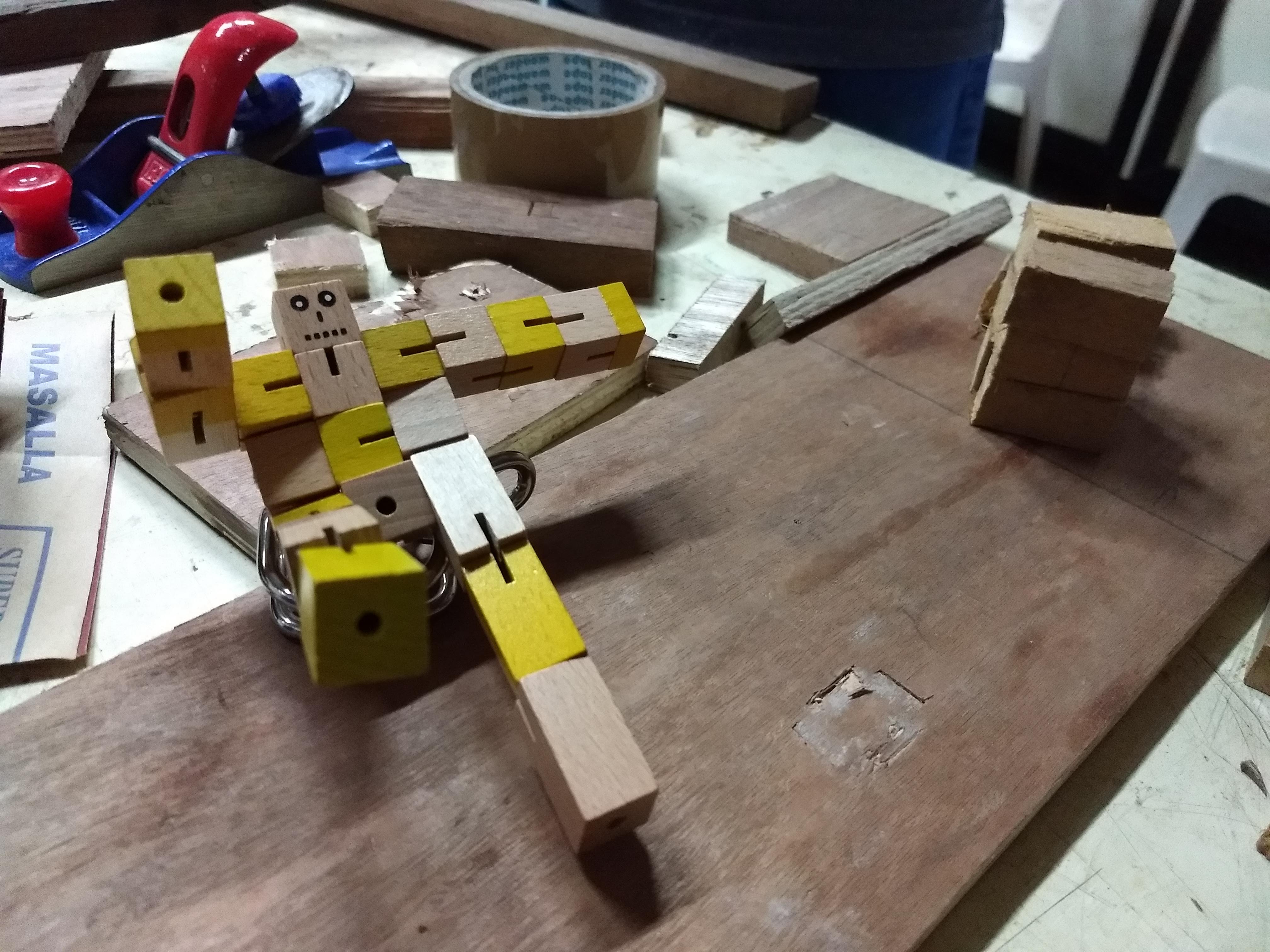
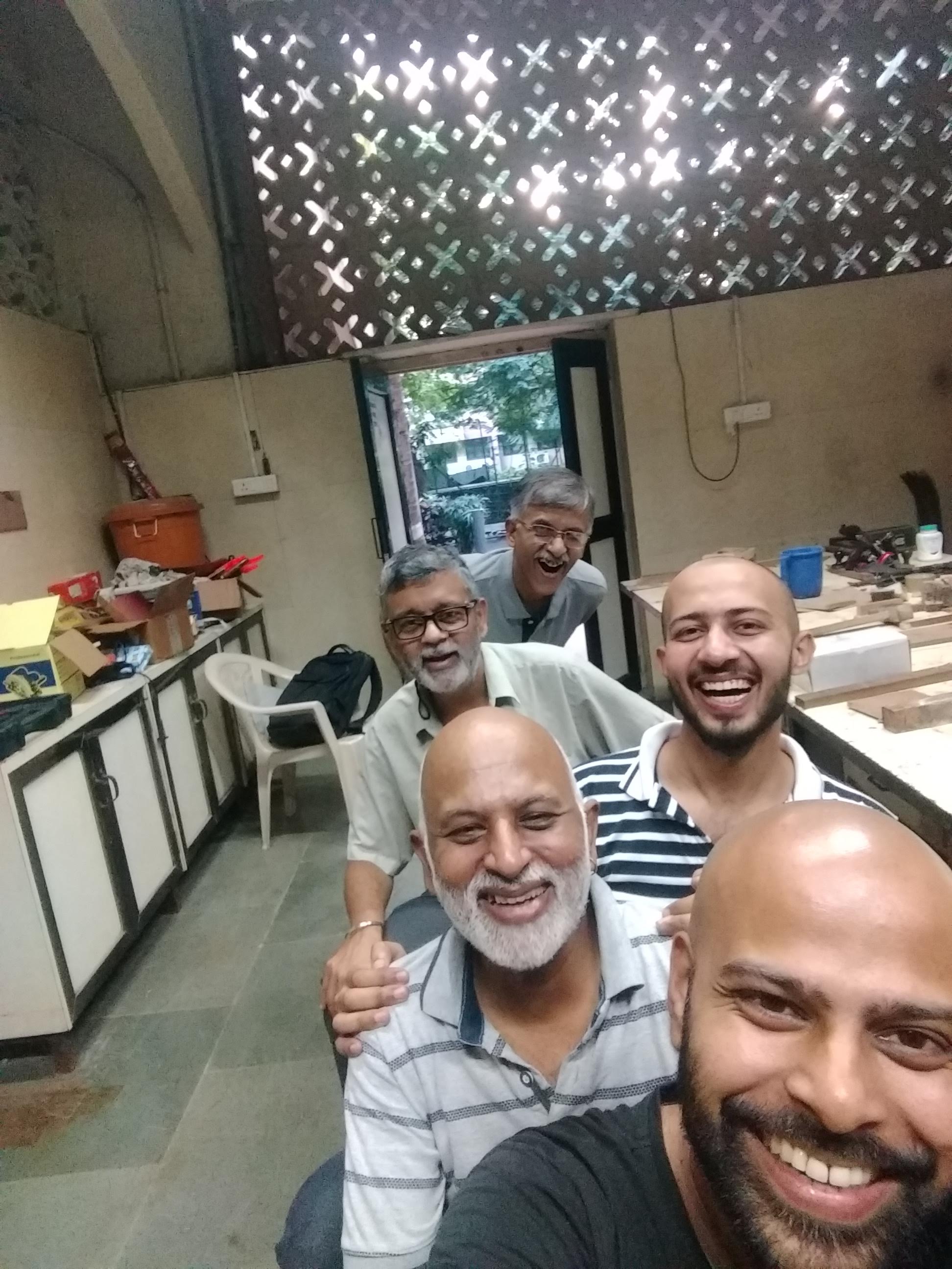
We had a serendipitous surprise today. Four 8th graders visited for CUBE lab but they arrived early hence joined us to participate in the activity.
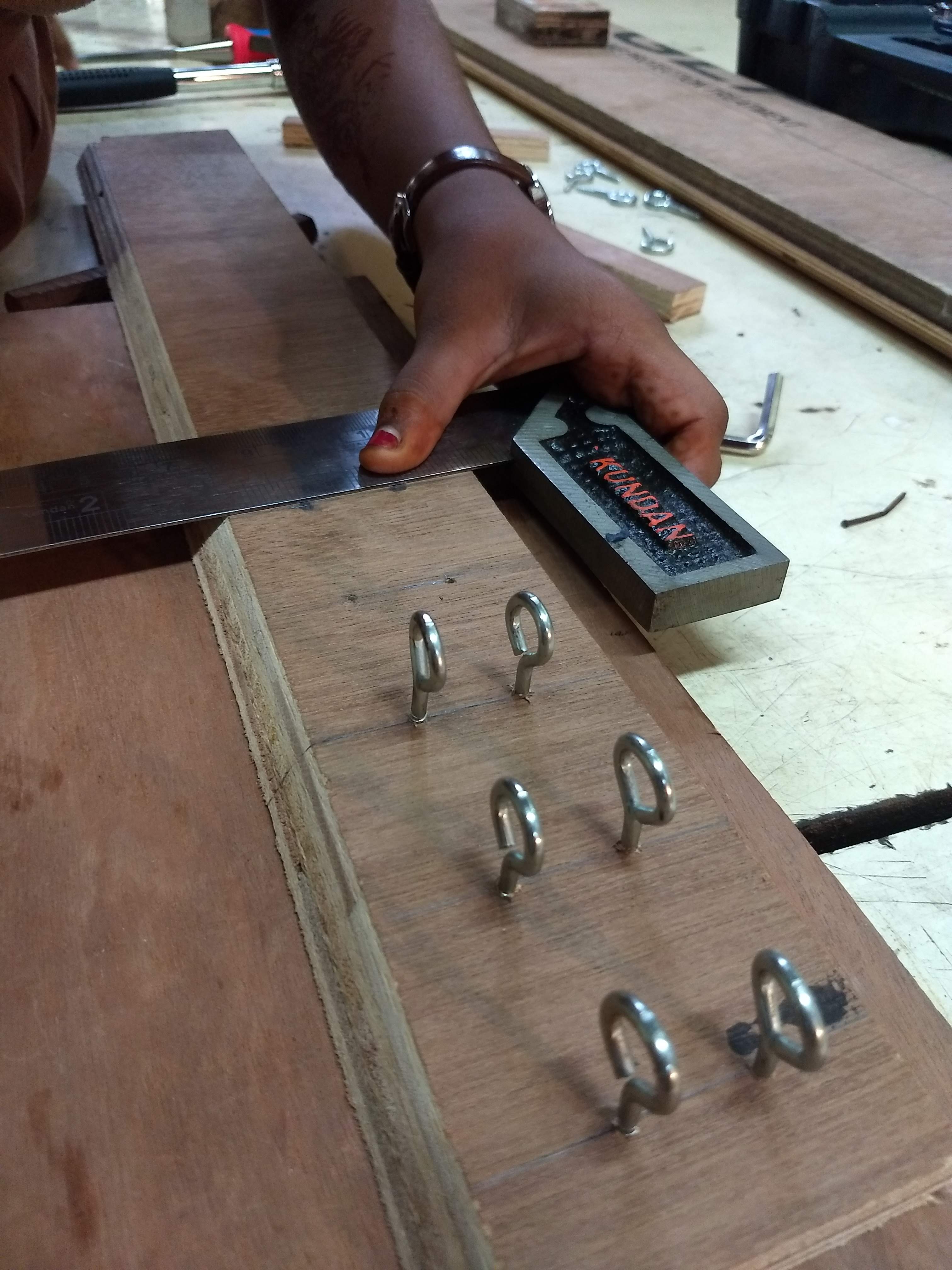
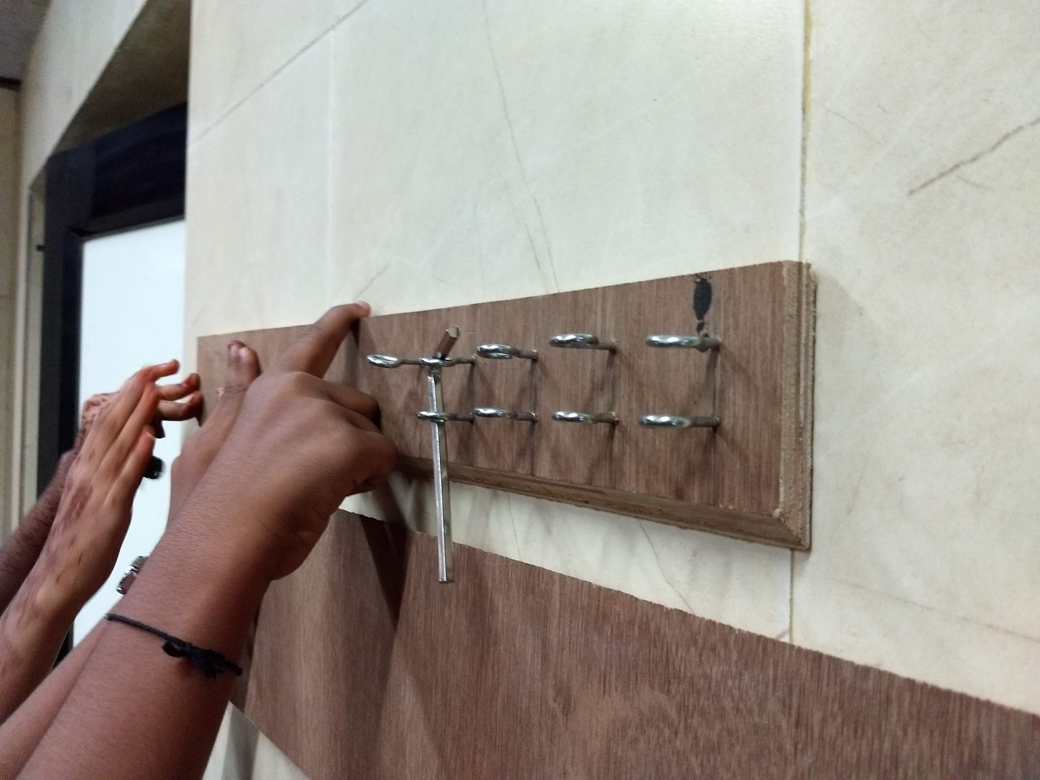
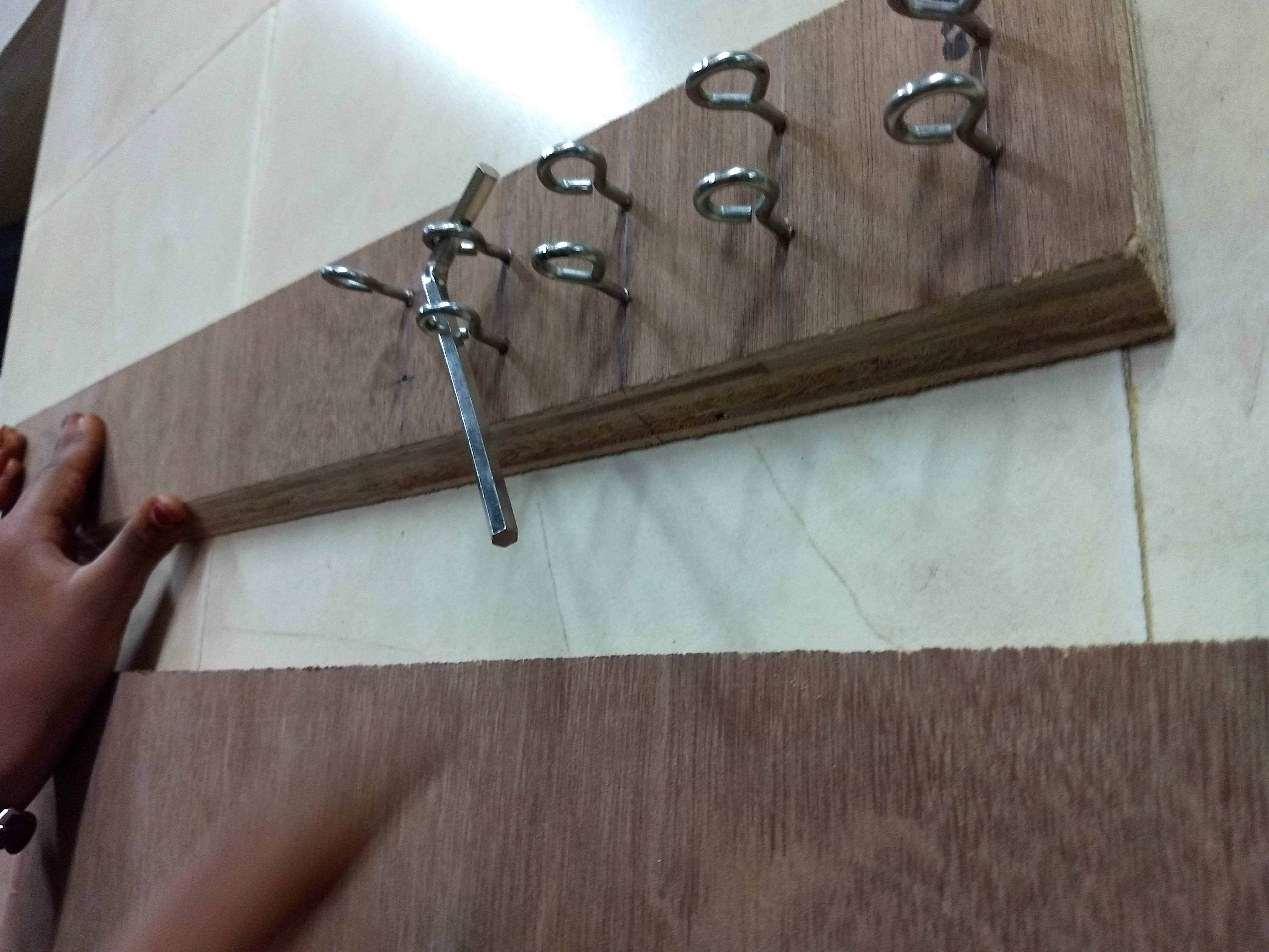
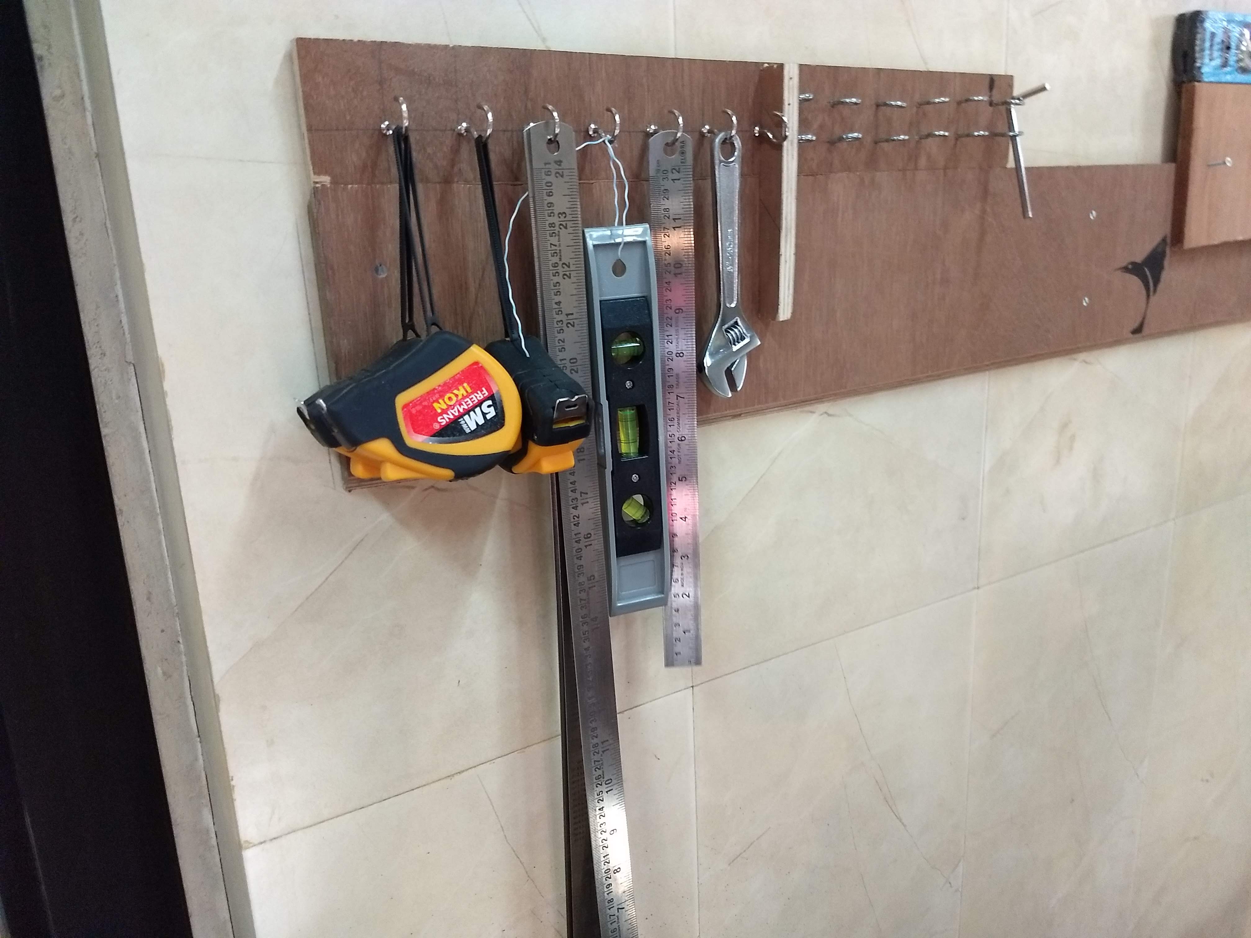
@Nagarjuna suggested them the project to design the organizer using circular hooks. They happily agreed to participate. Here is the glimpses of their work:
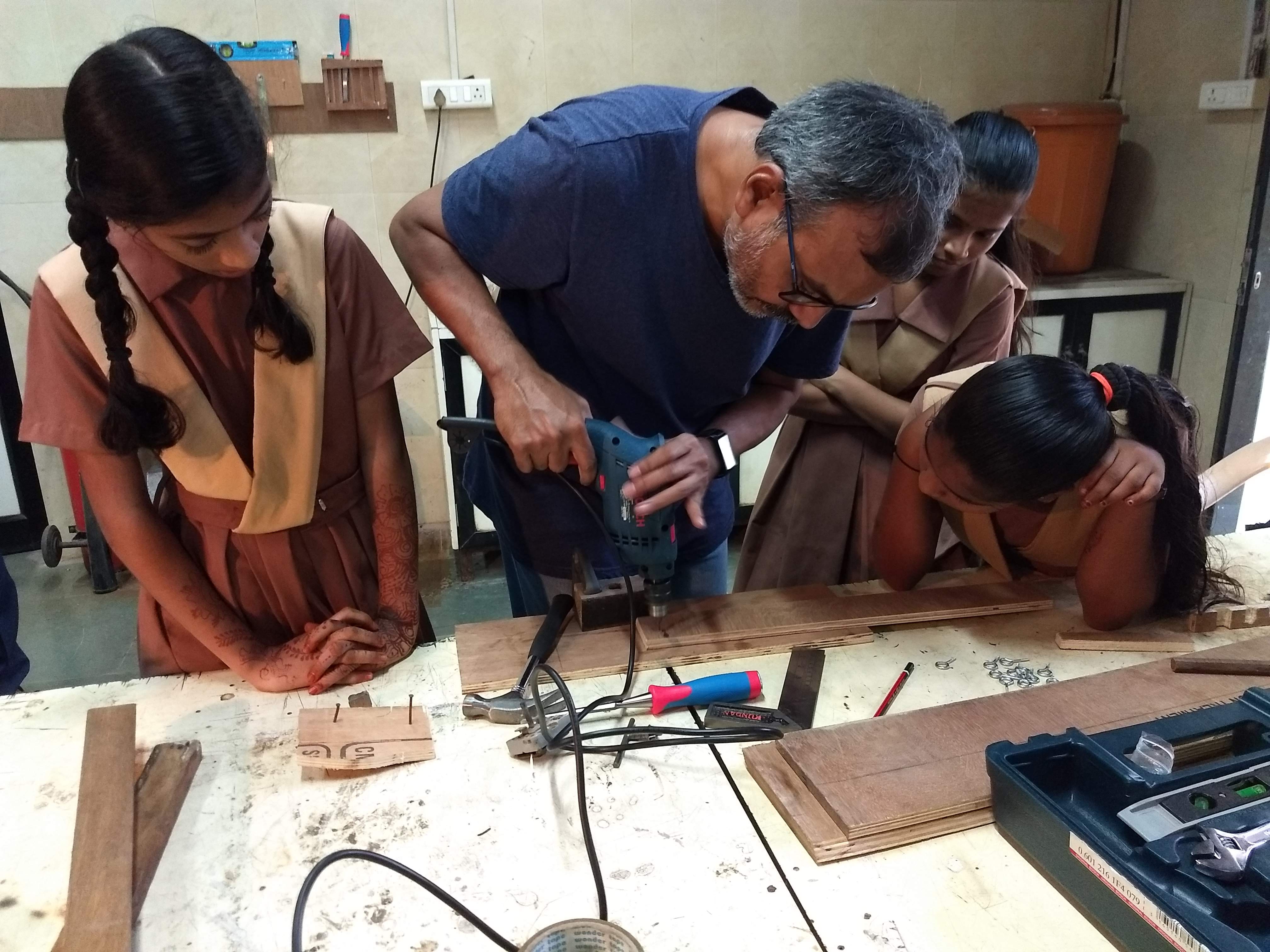
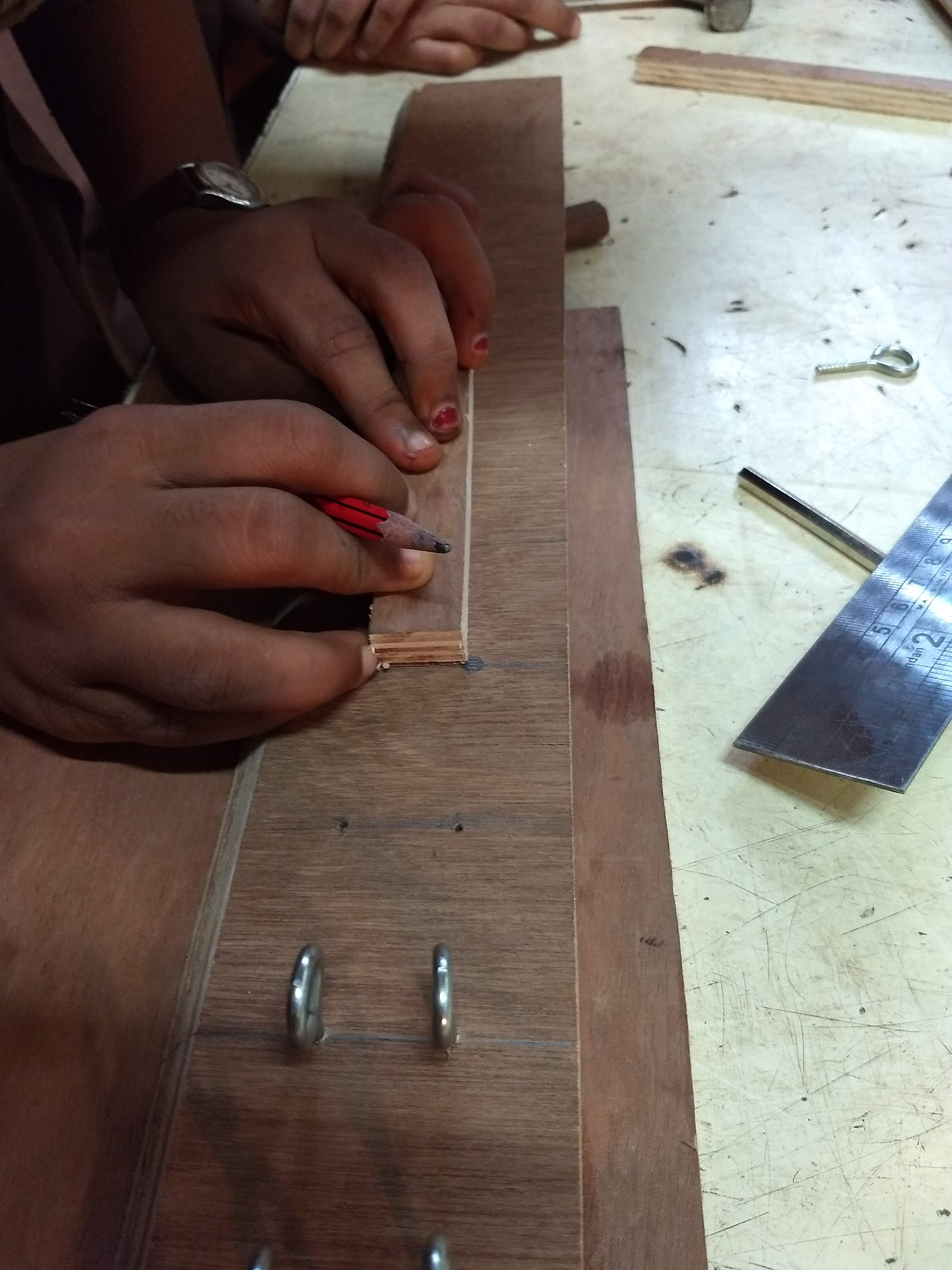
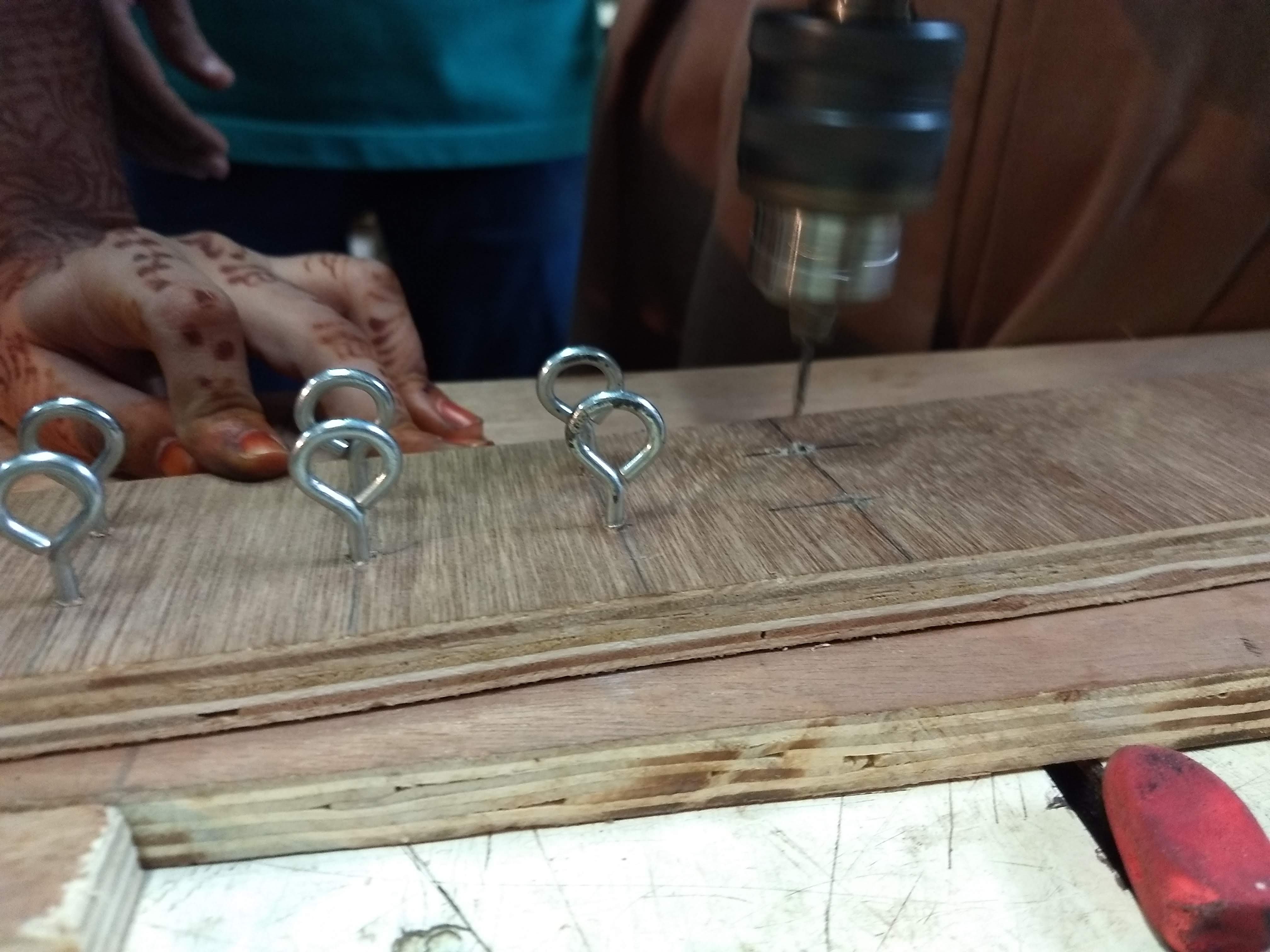
Marking the holes and using the drill to make the same. This is the first time these students are using the power tool and hence they were really excited.
So you keep repeating the same process, marking, drilling, putting the hooks to get two rows of hooks. The children were taking turns in the process and exchanging roles and responsibilities.
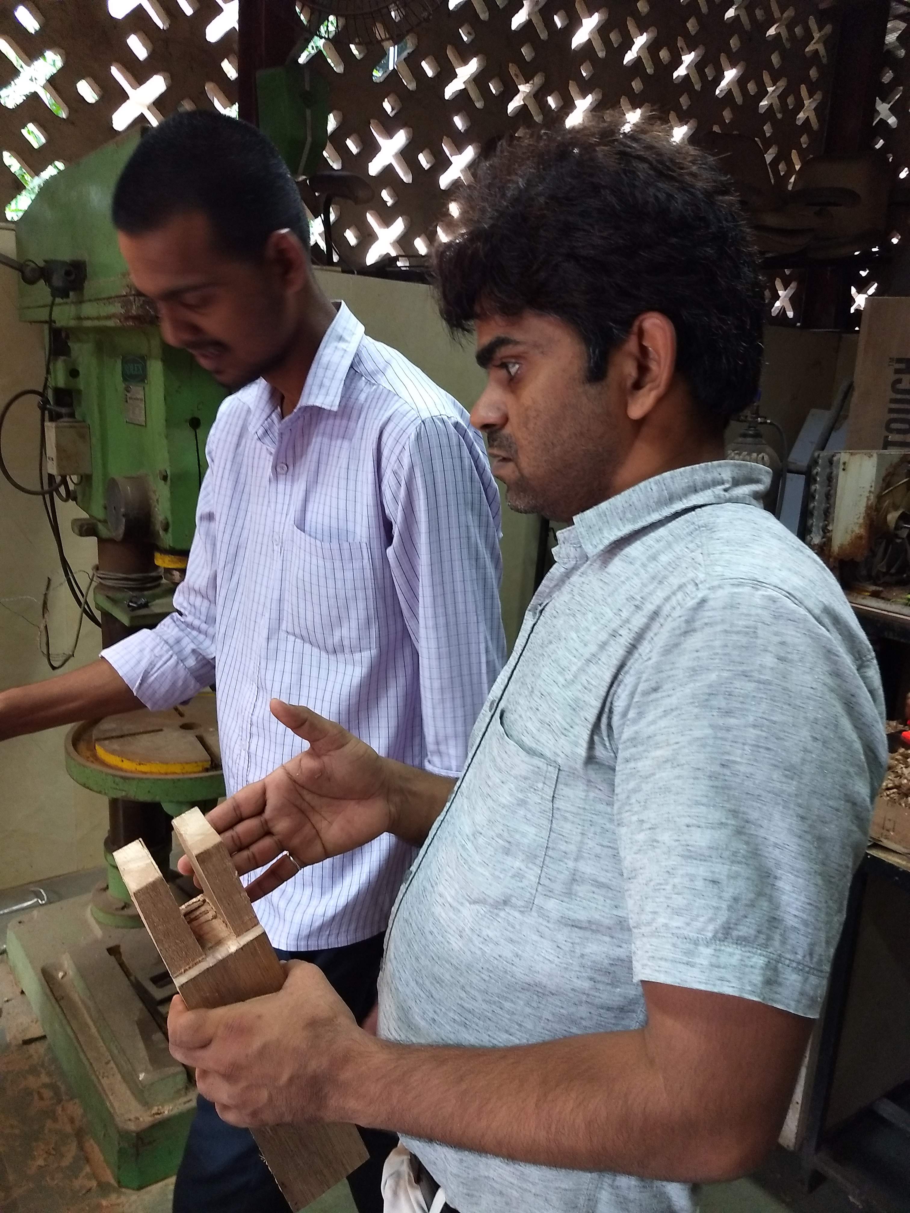
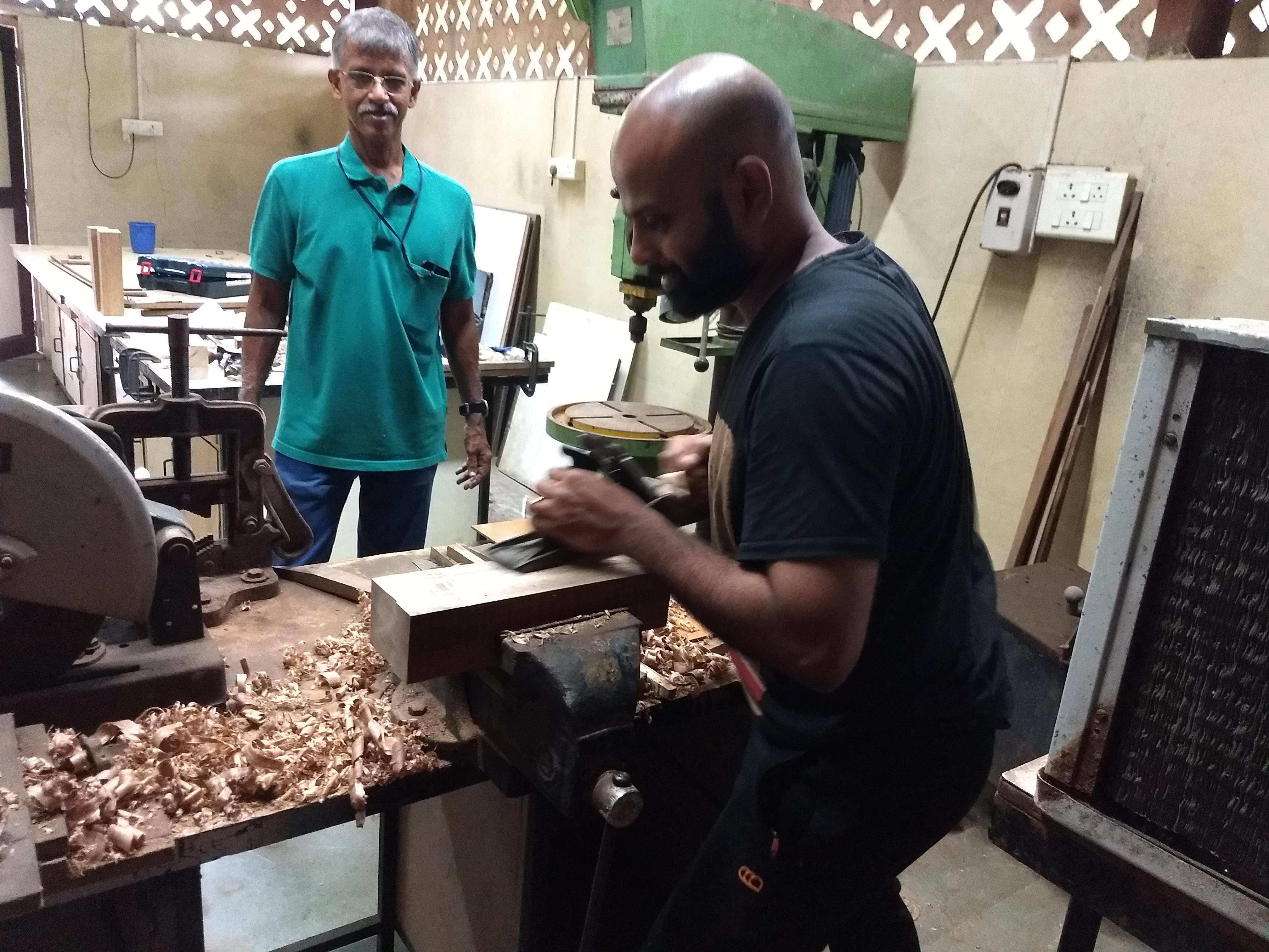
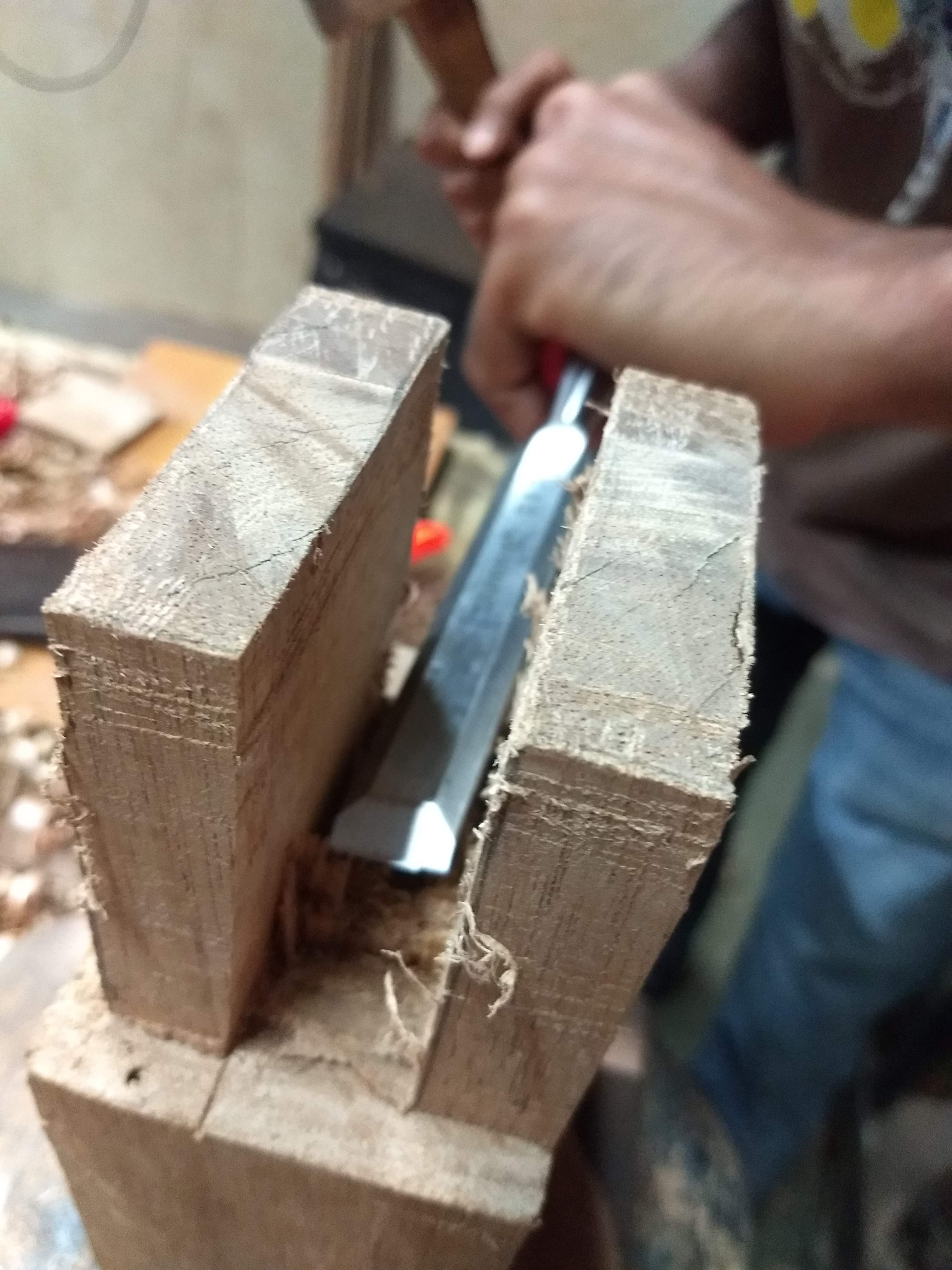
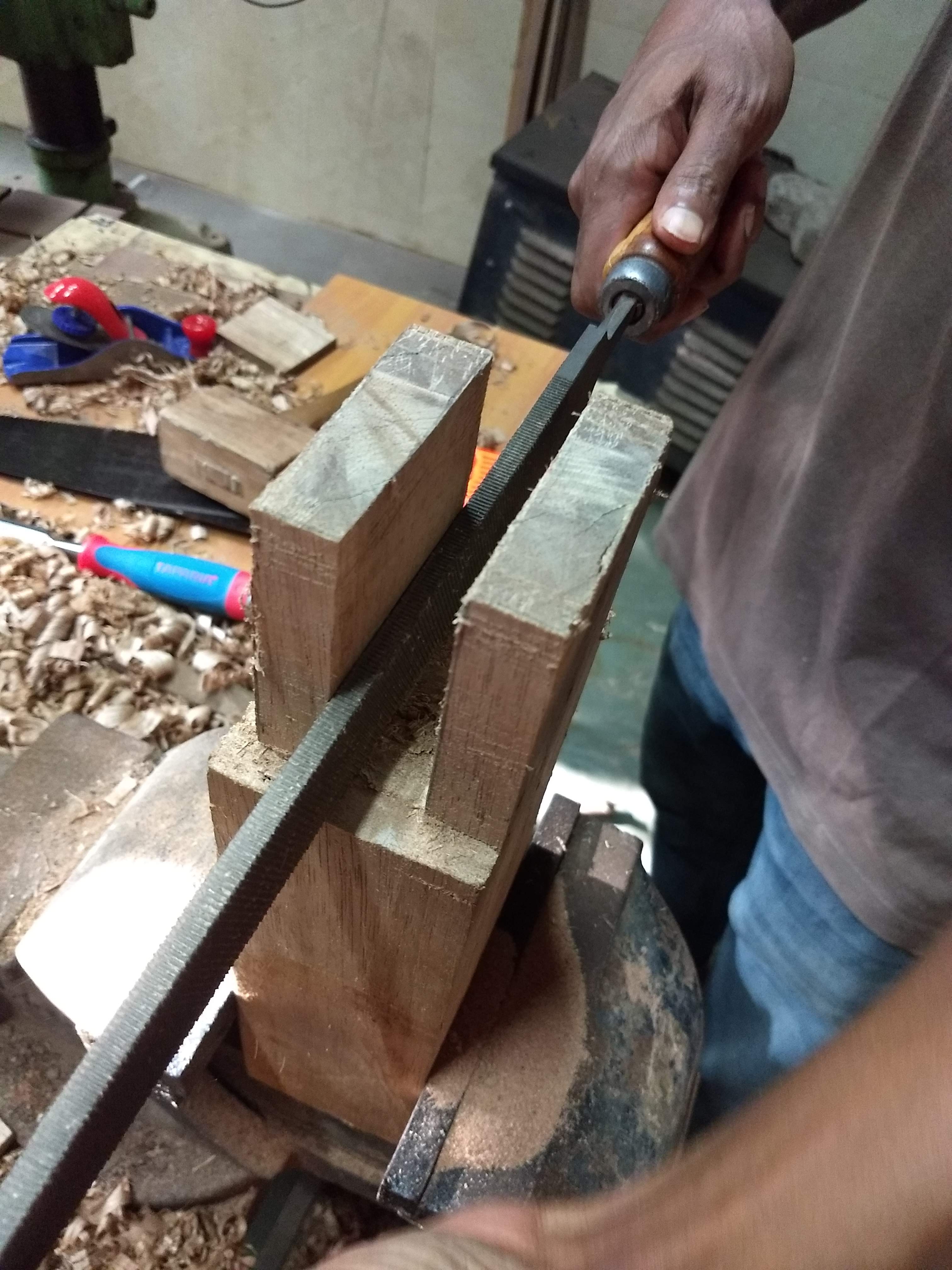
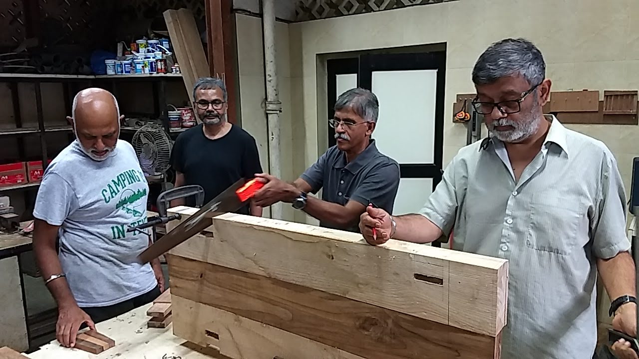
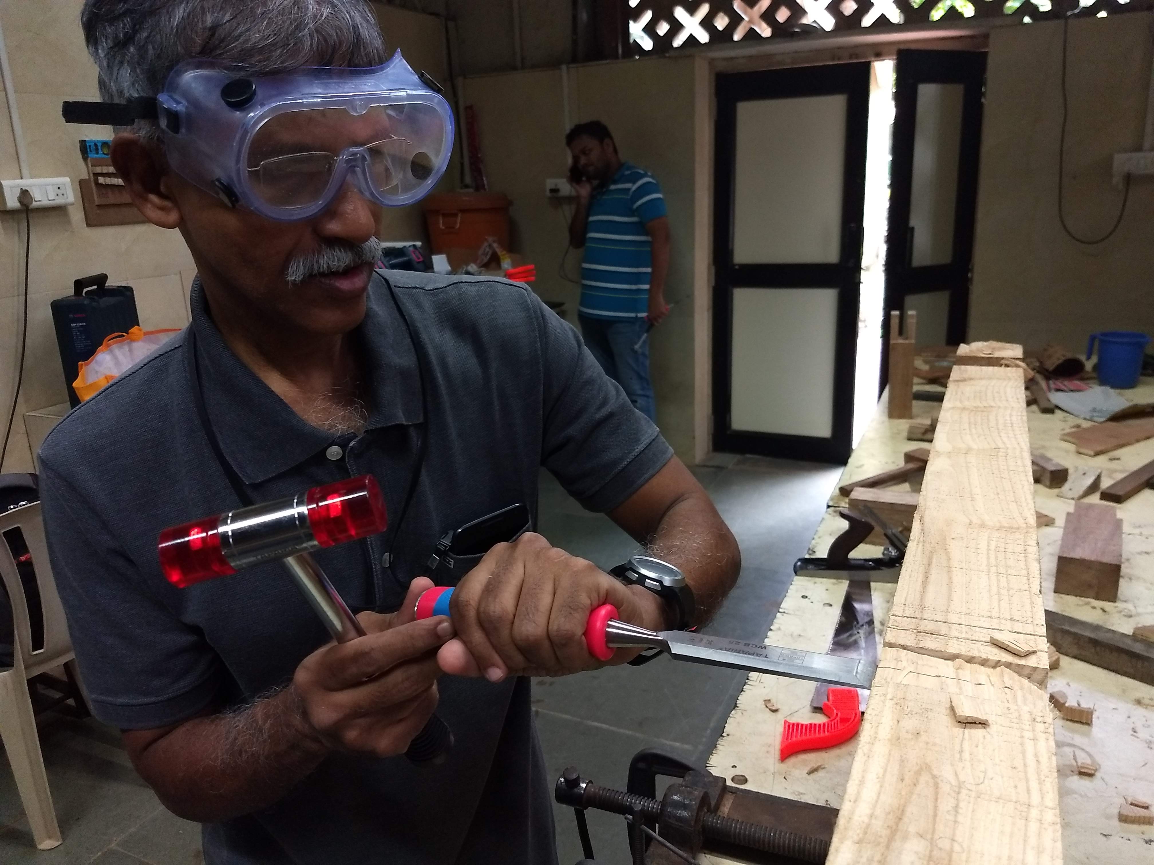
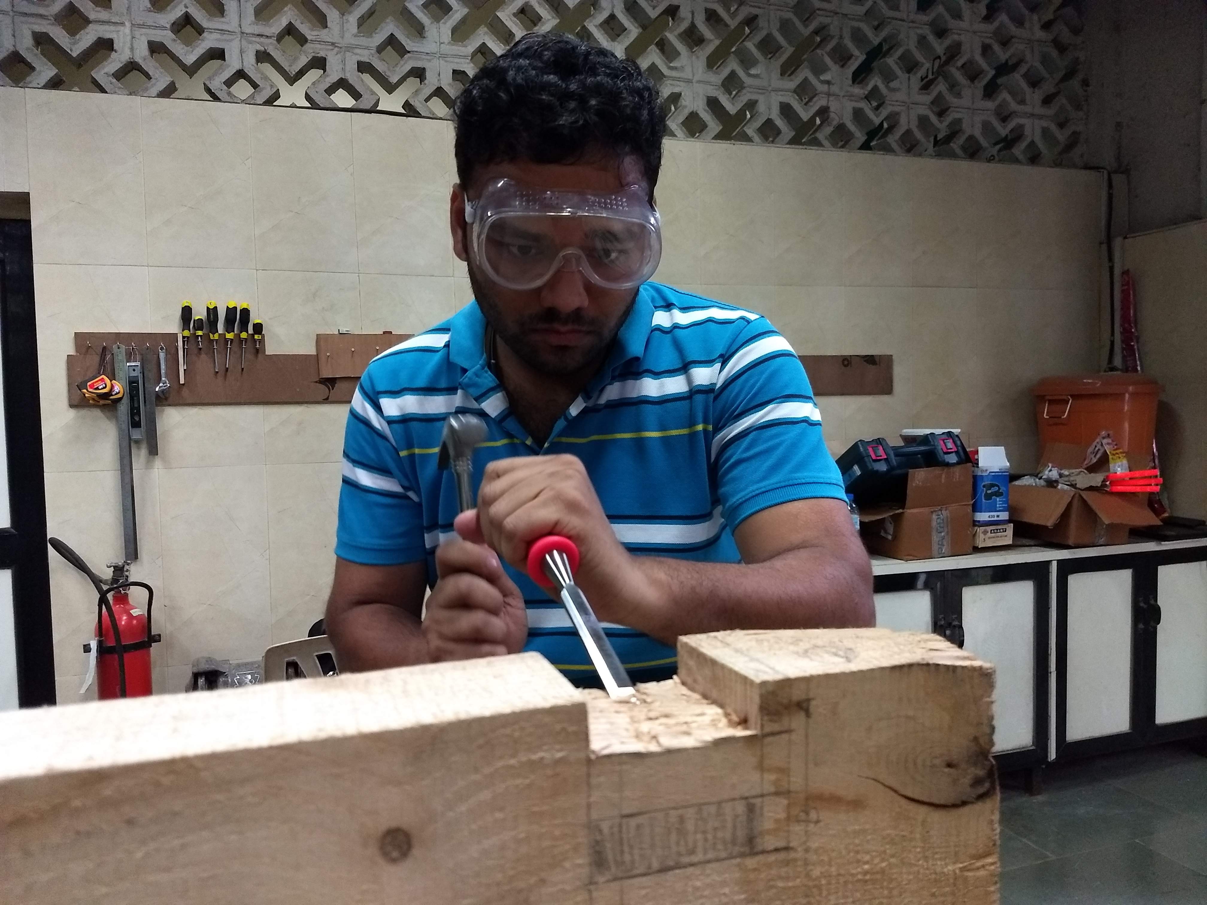
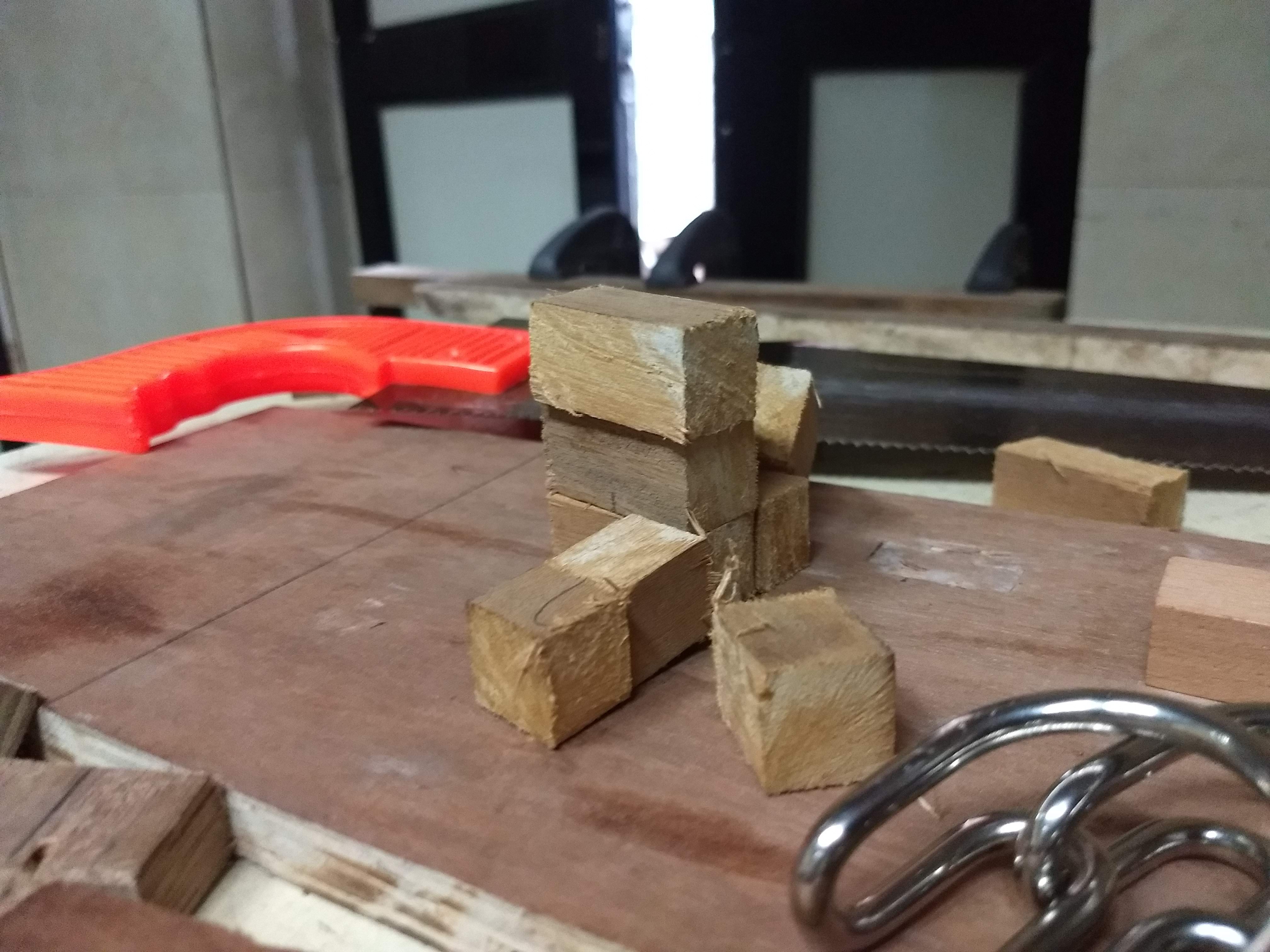
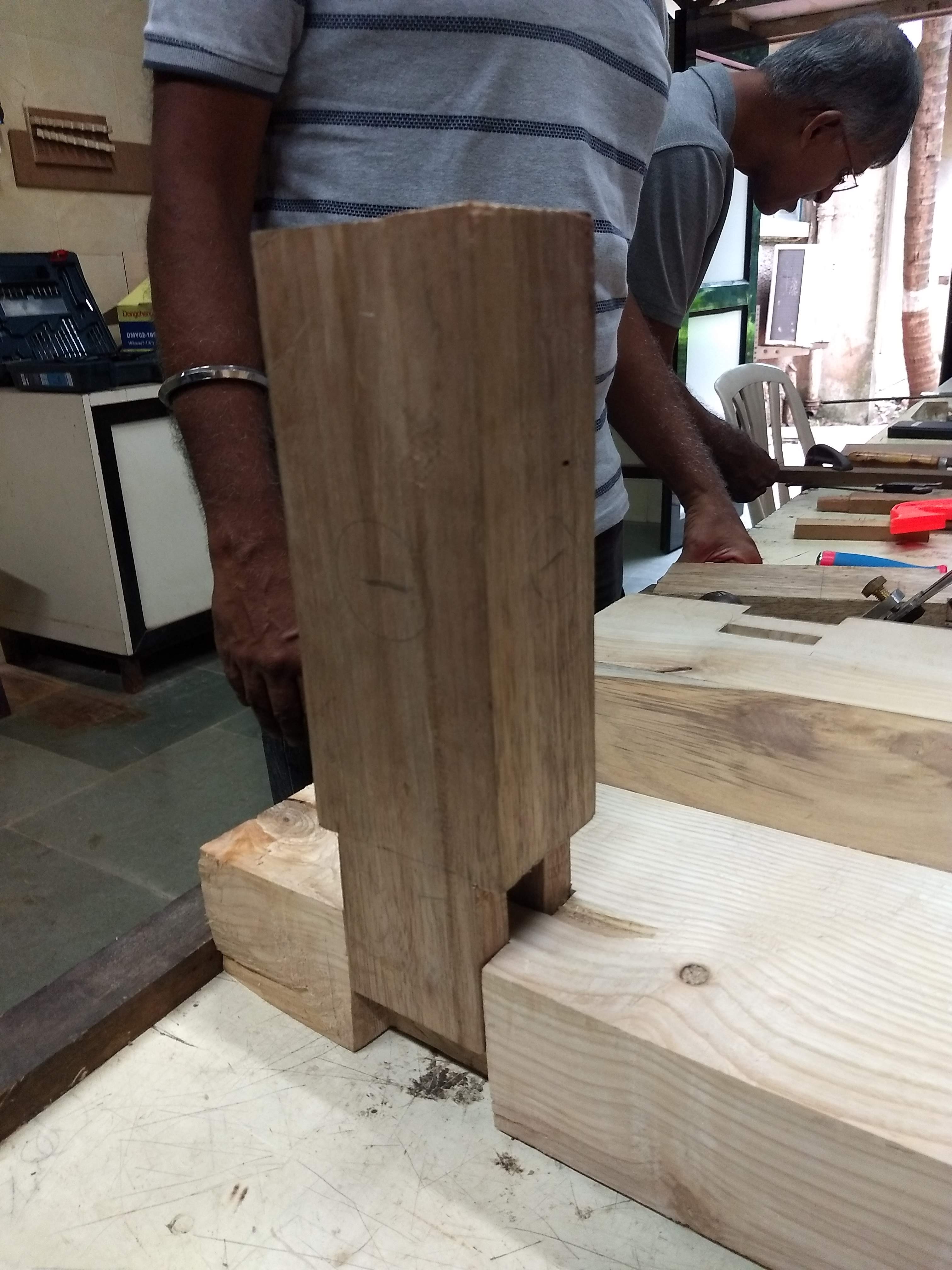
In the parallel universe :D, the other members were re-working the legs and making a connector sort of structure which can be plugged in the 3-inch tabletop.
The work involved use of a multitude of tools, including a circular saw, hand saw and chisel to finally convert the cuboid legs into the requisite form.
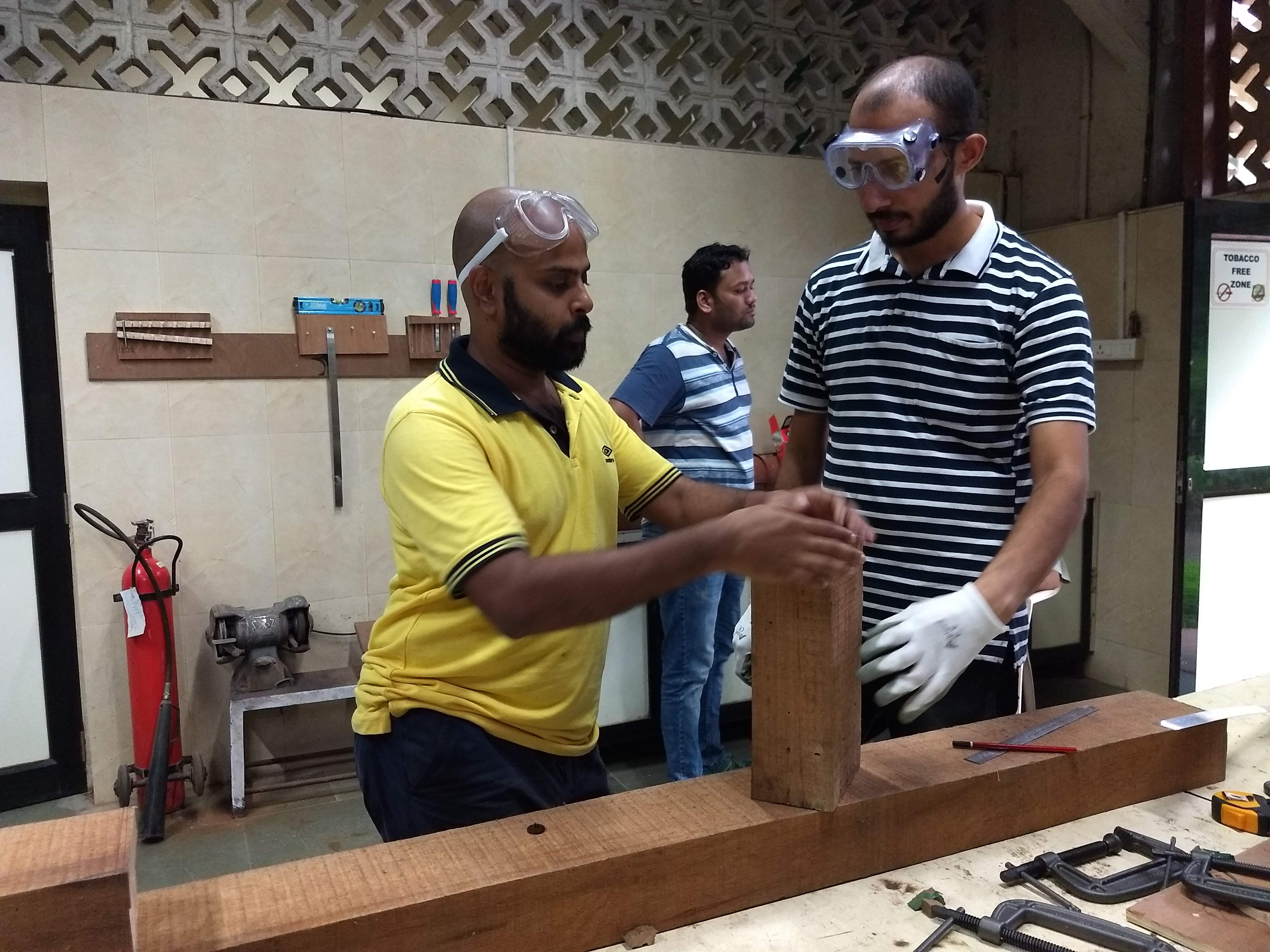
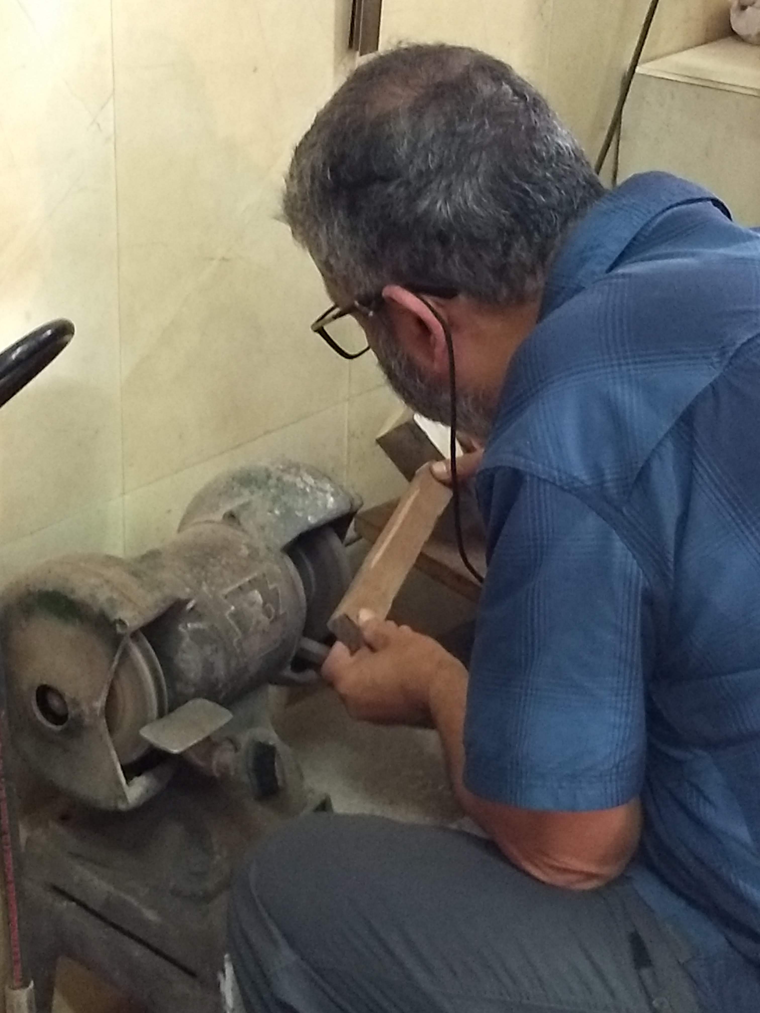
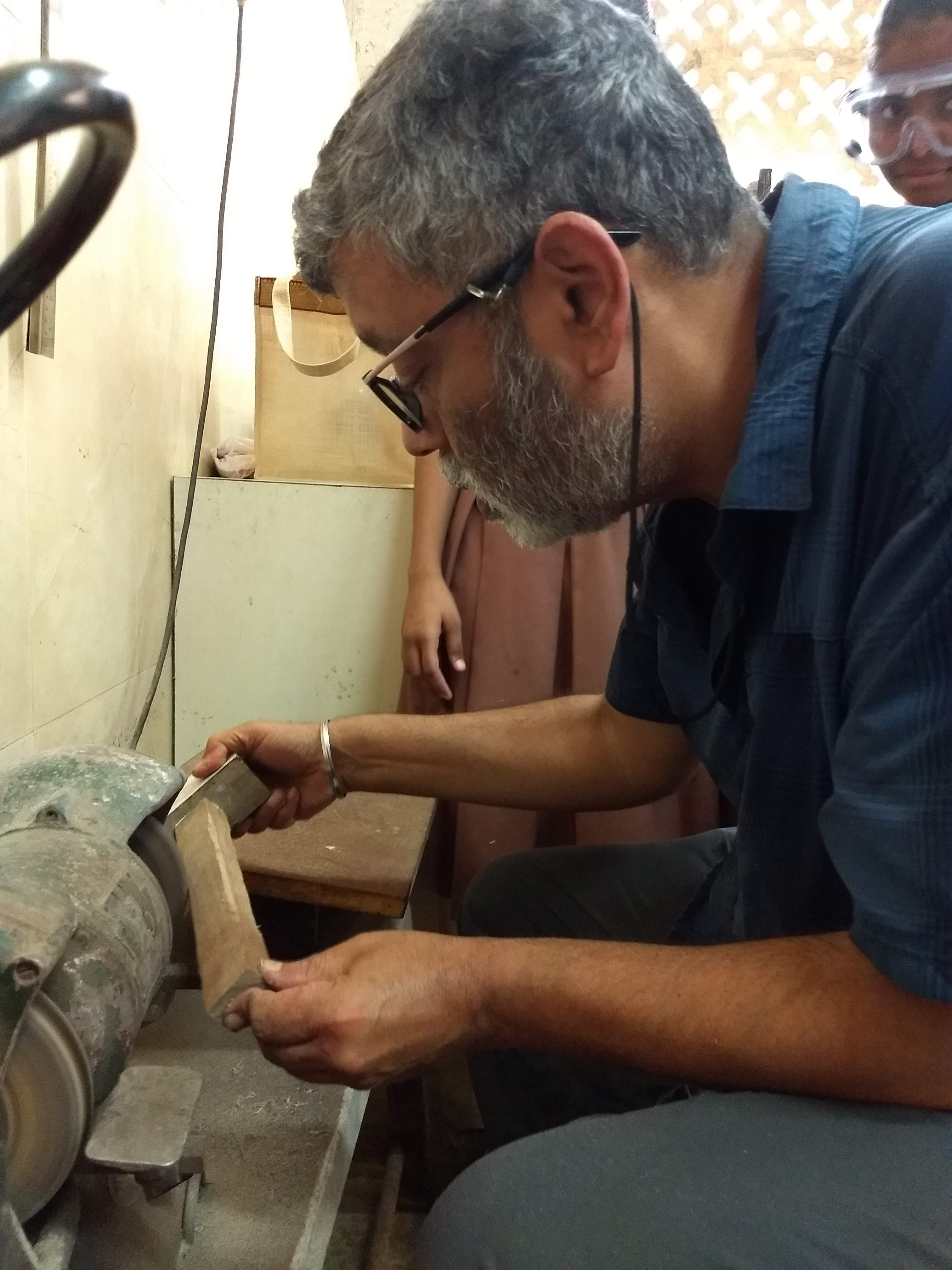
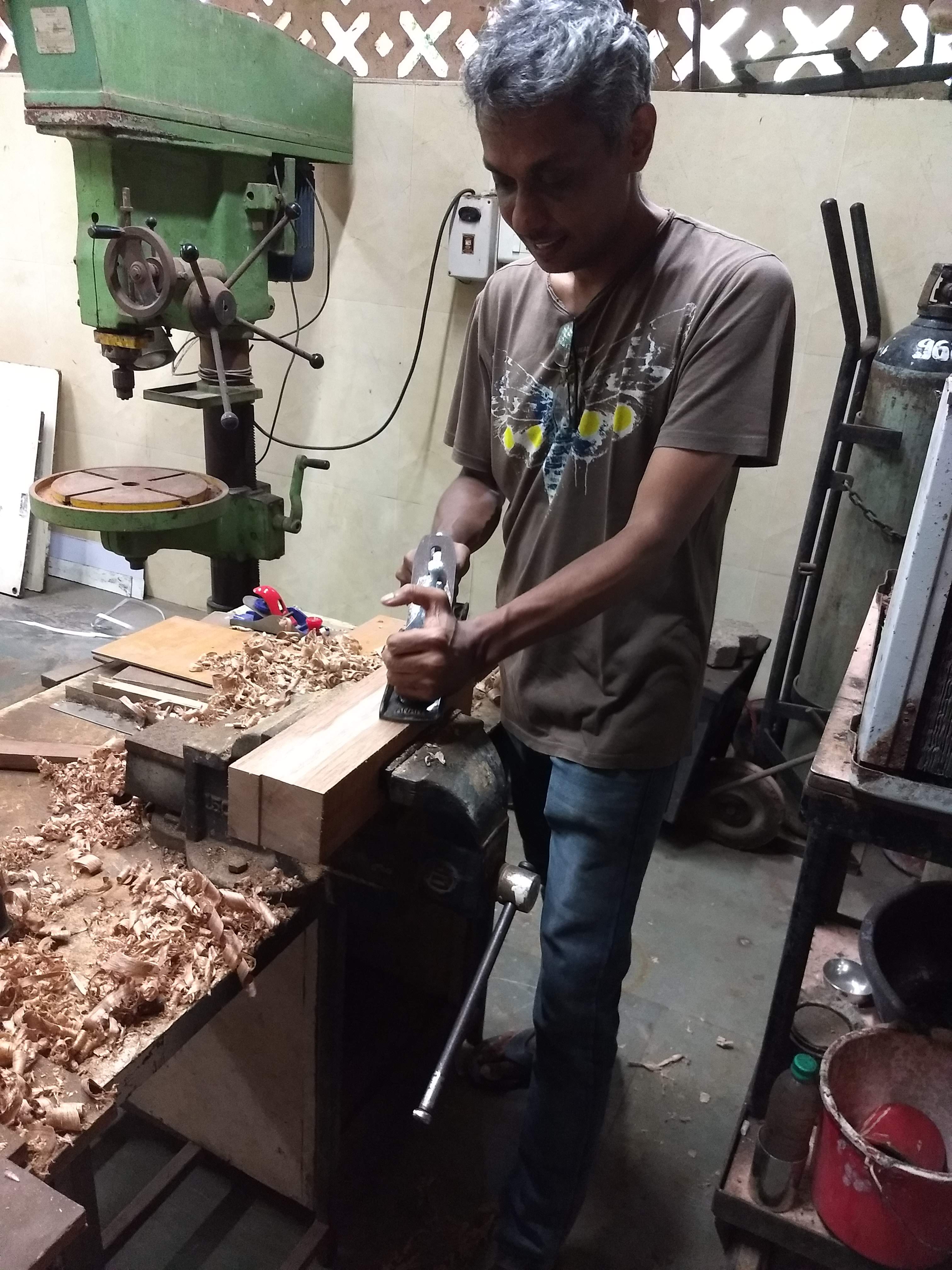
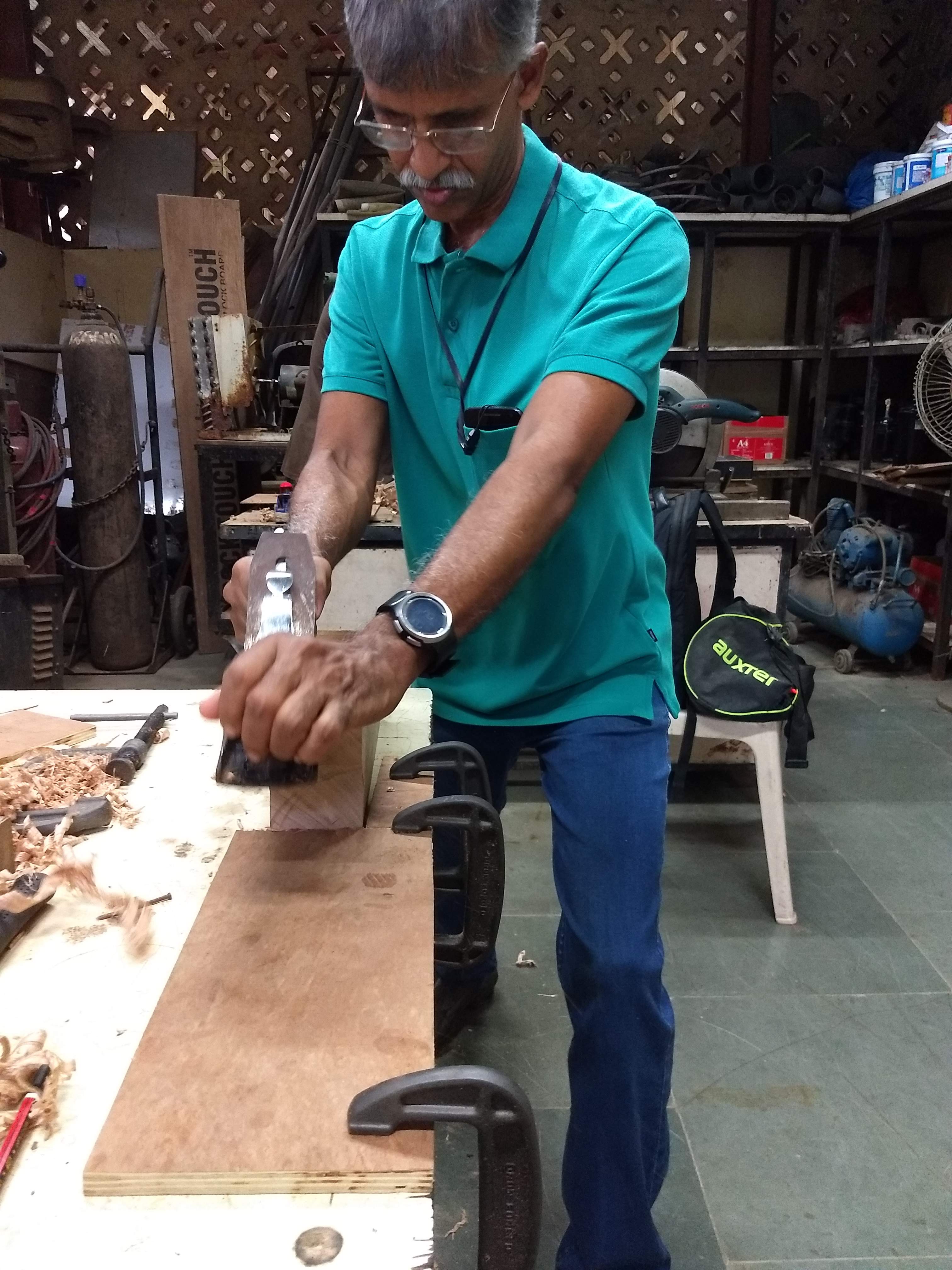
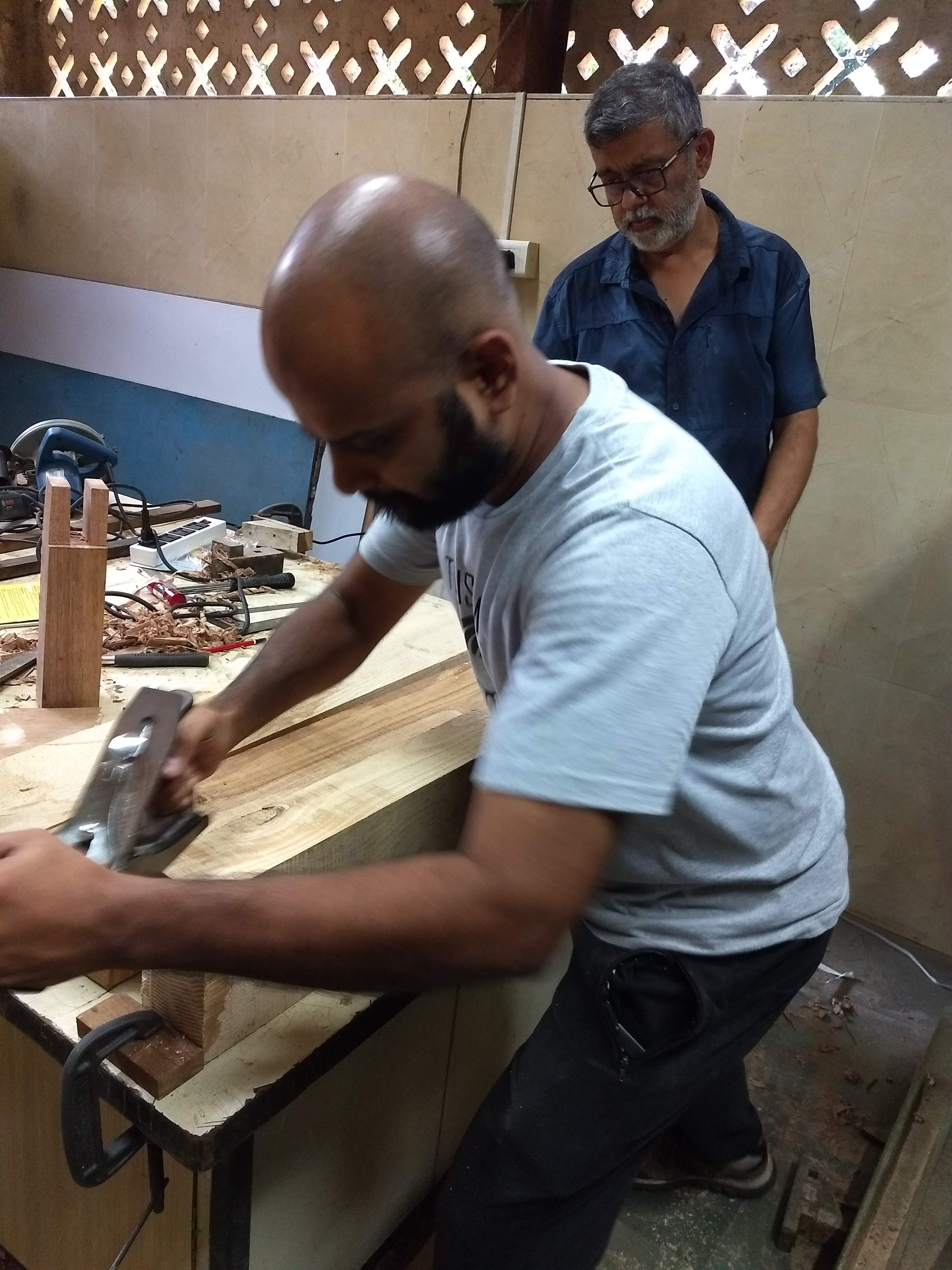
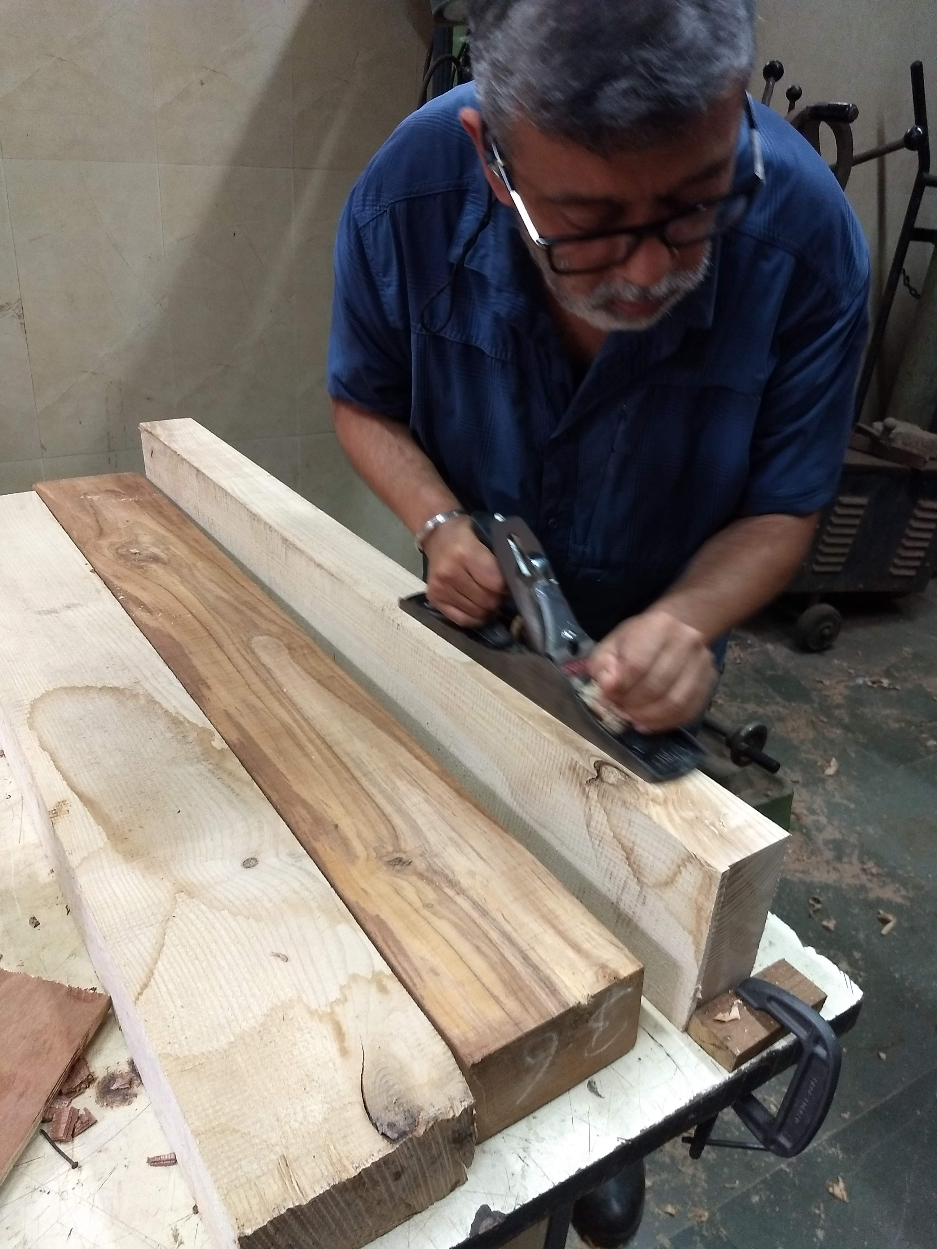
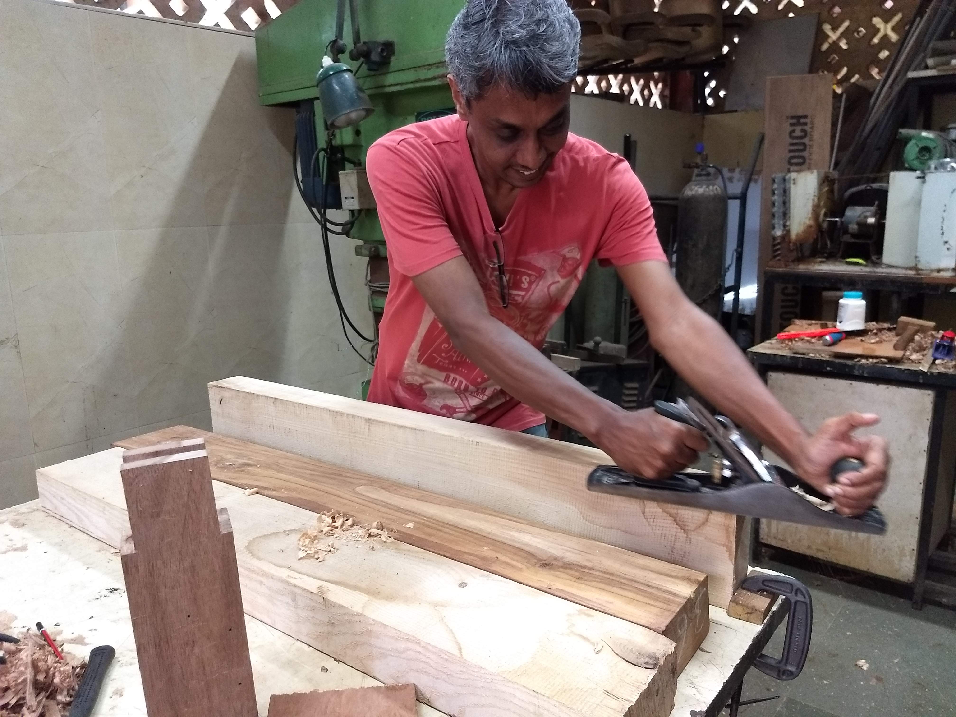
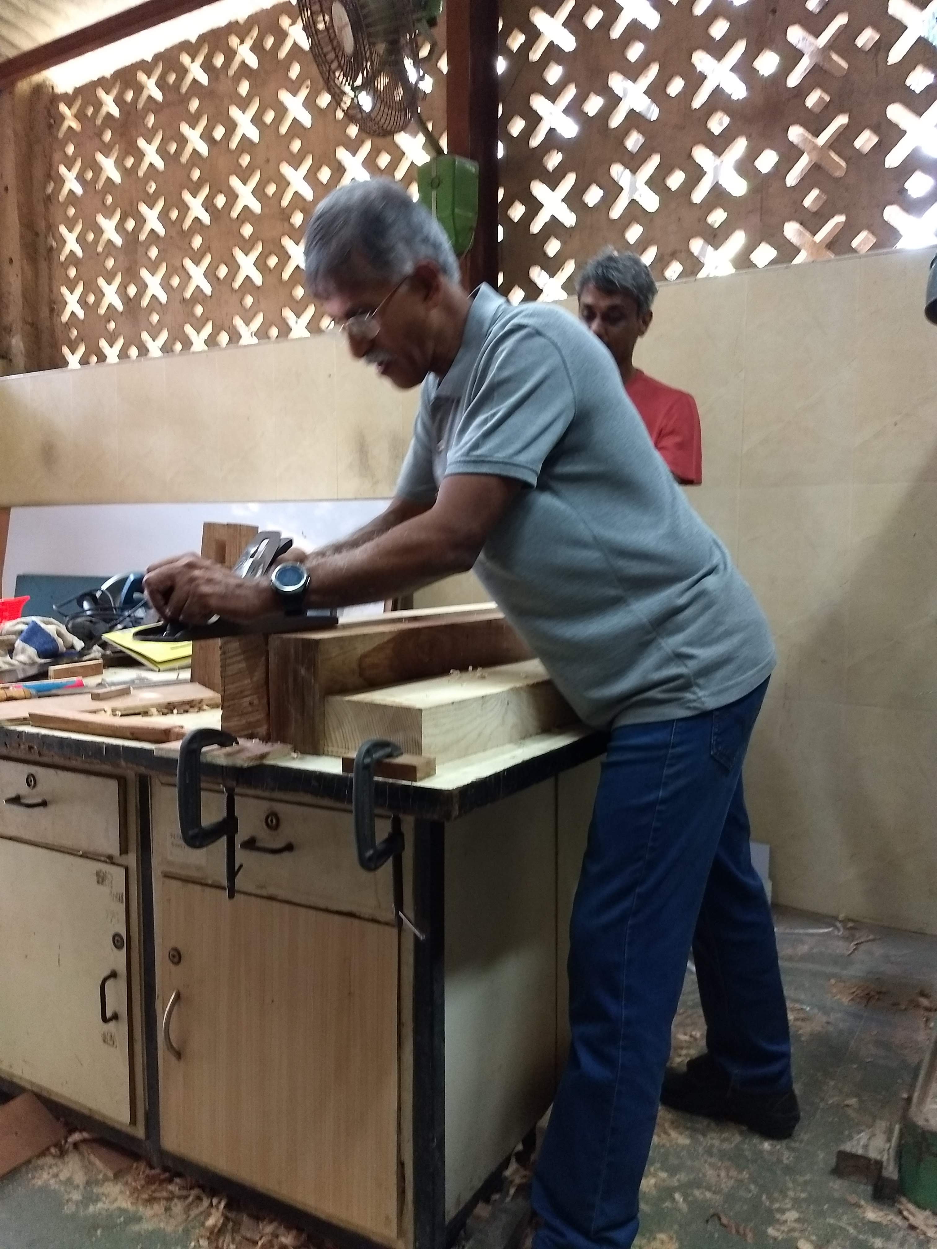
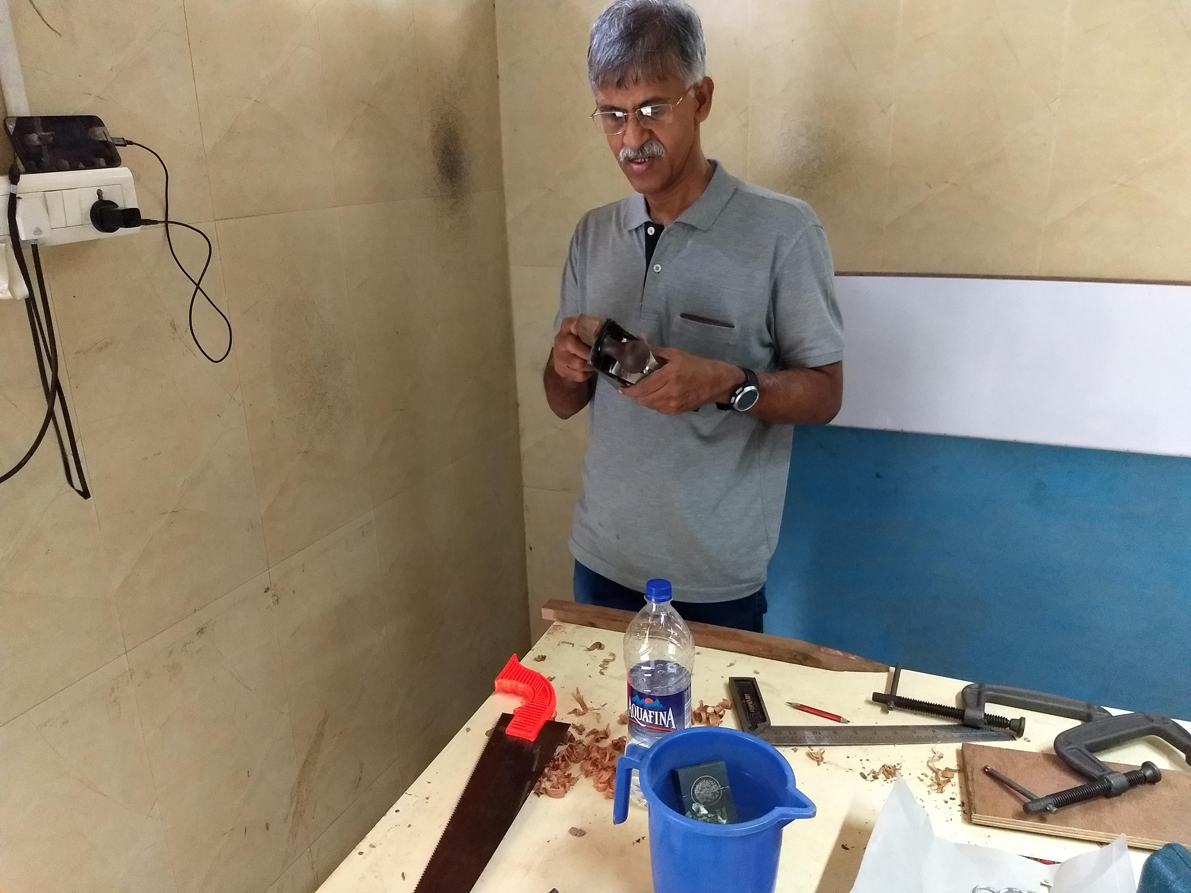
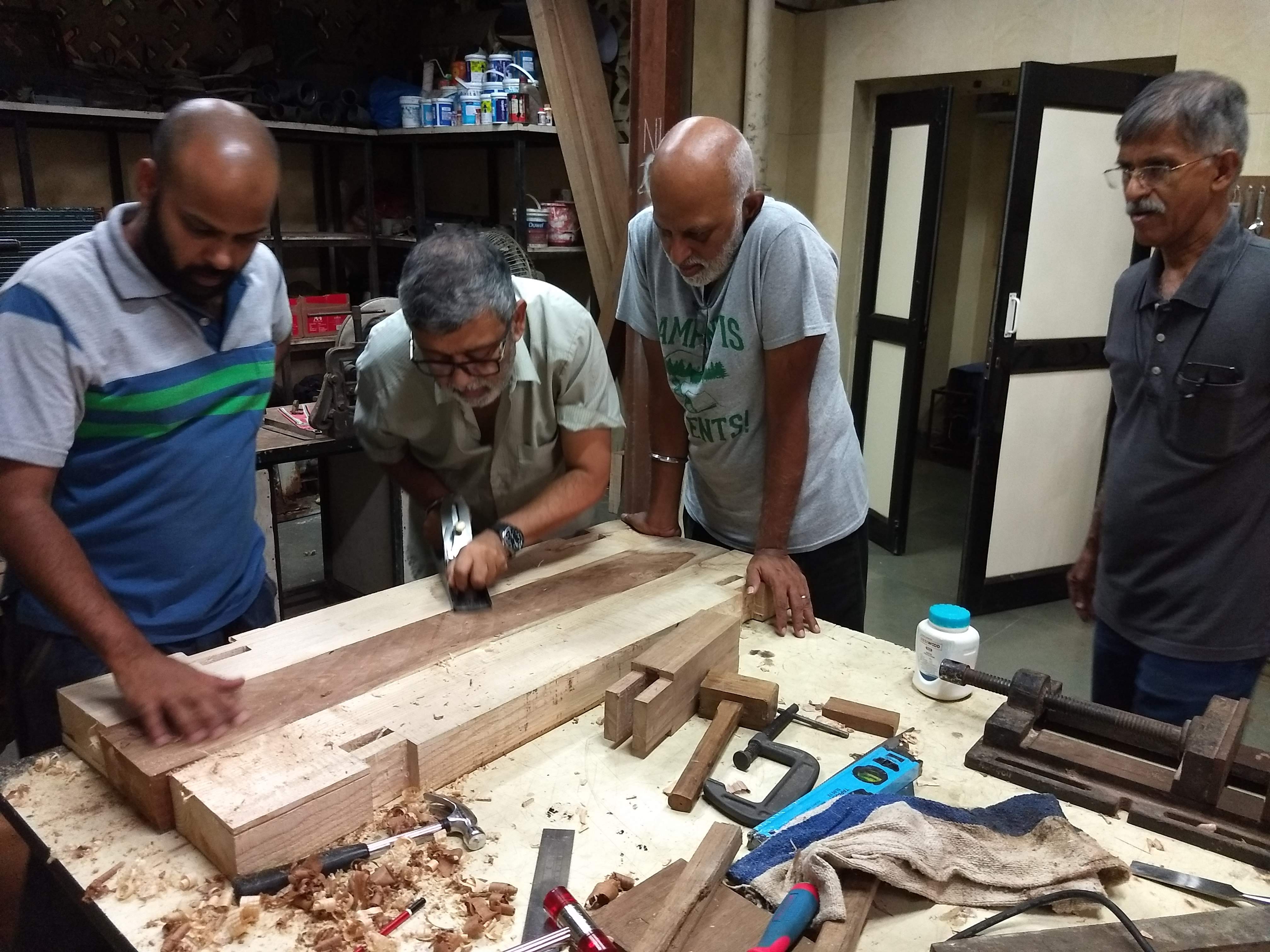
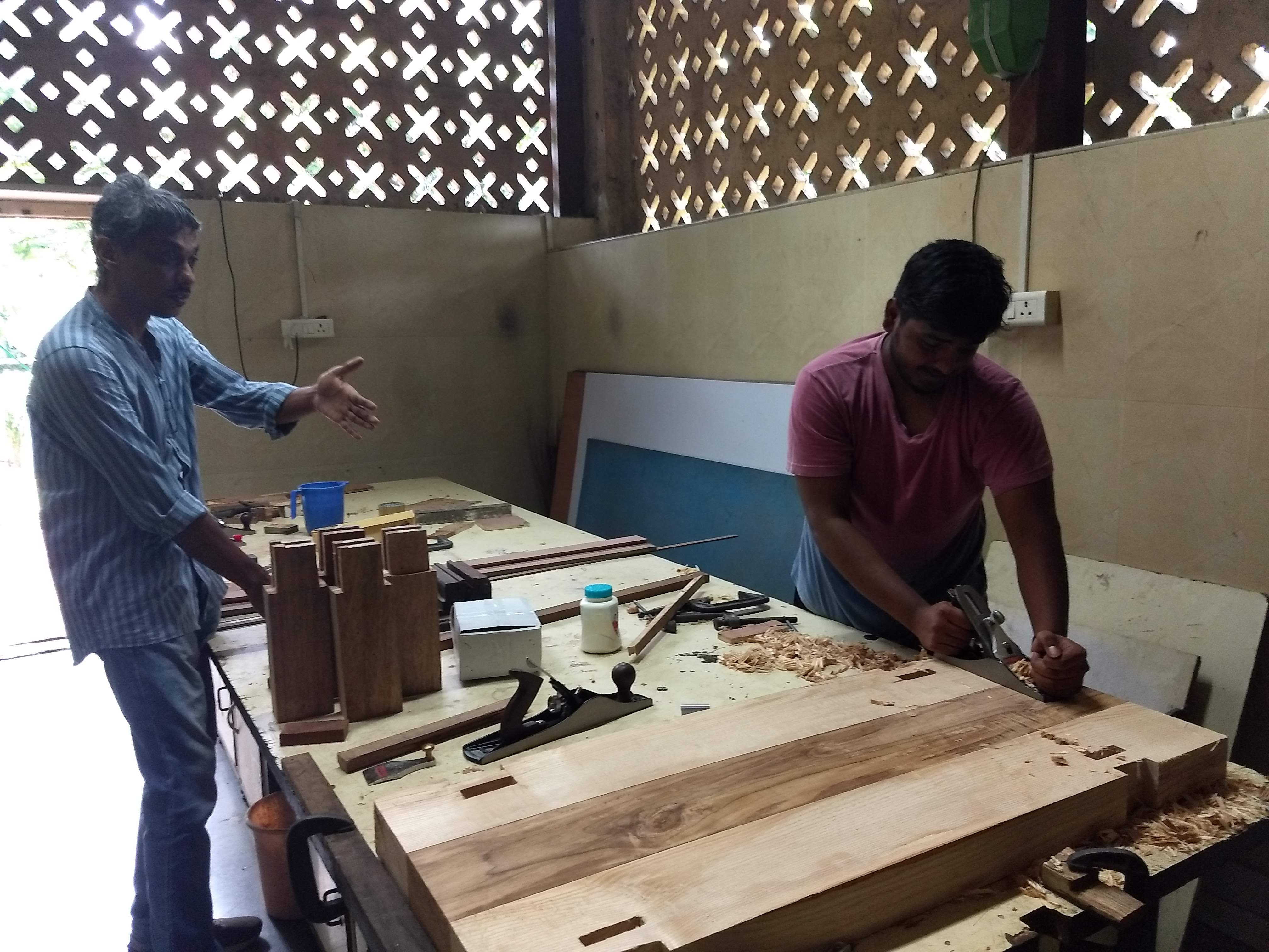
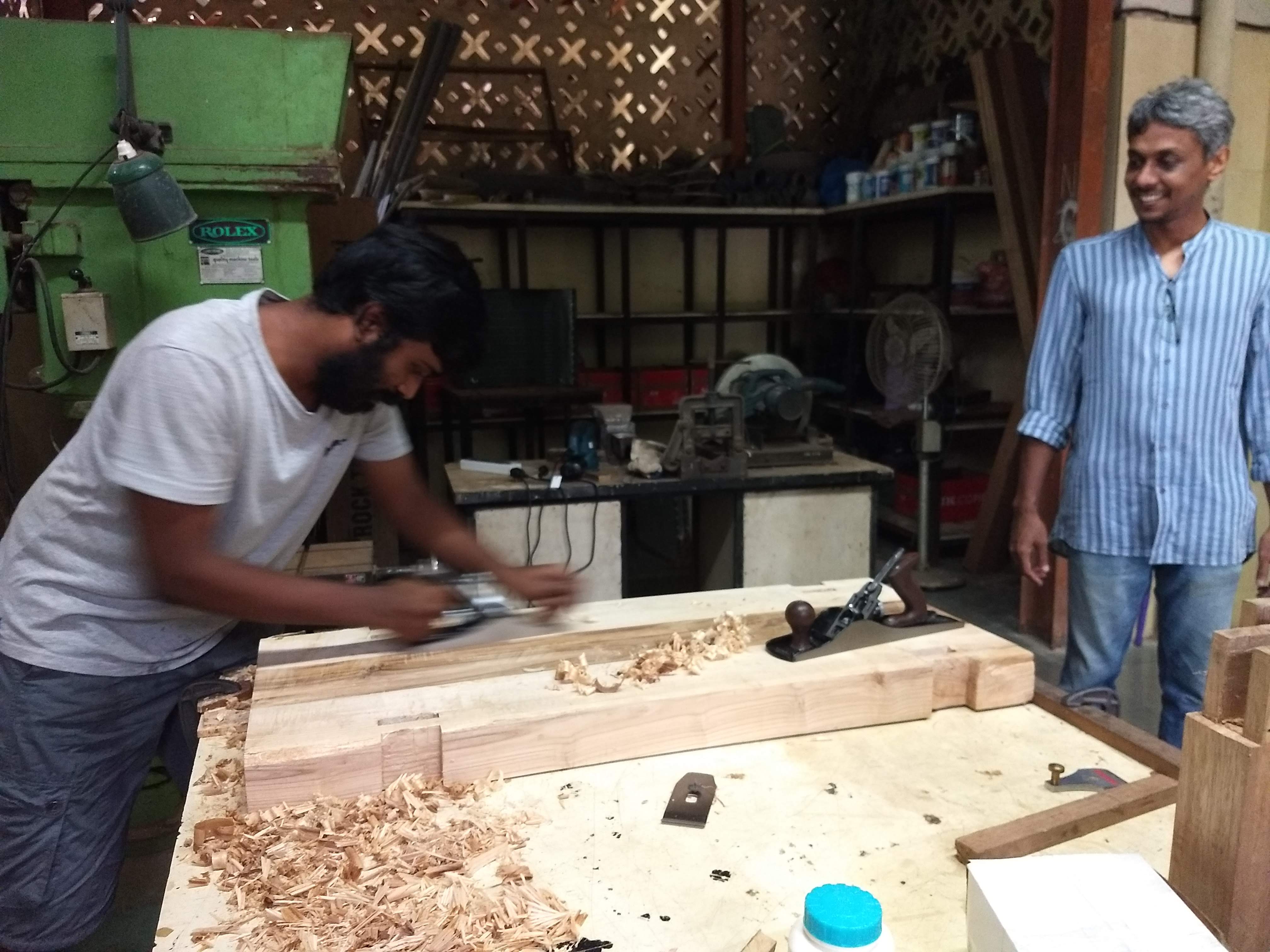
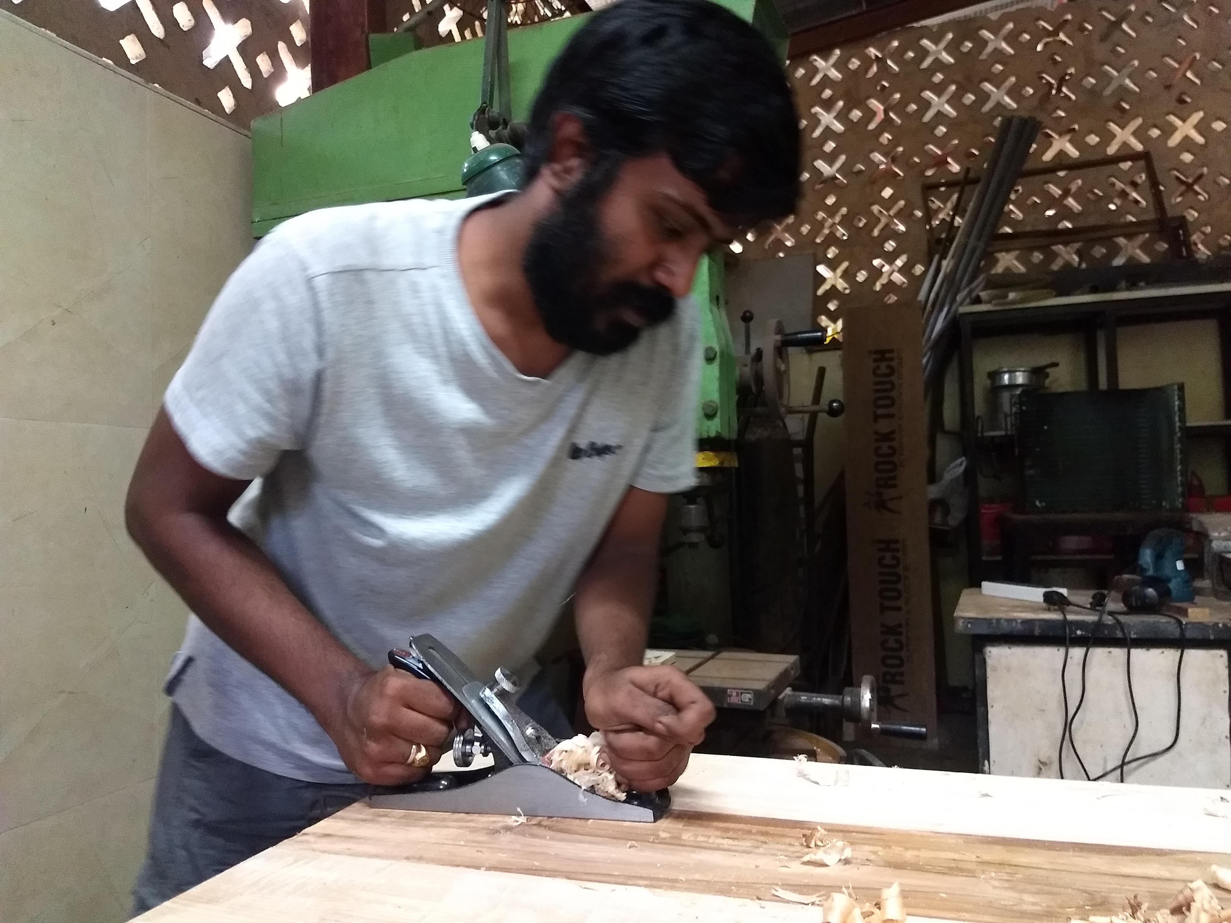
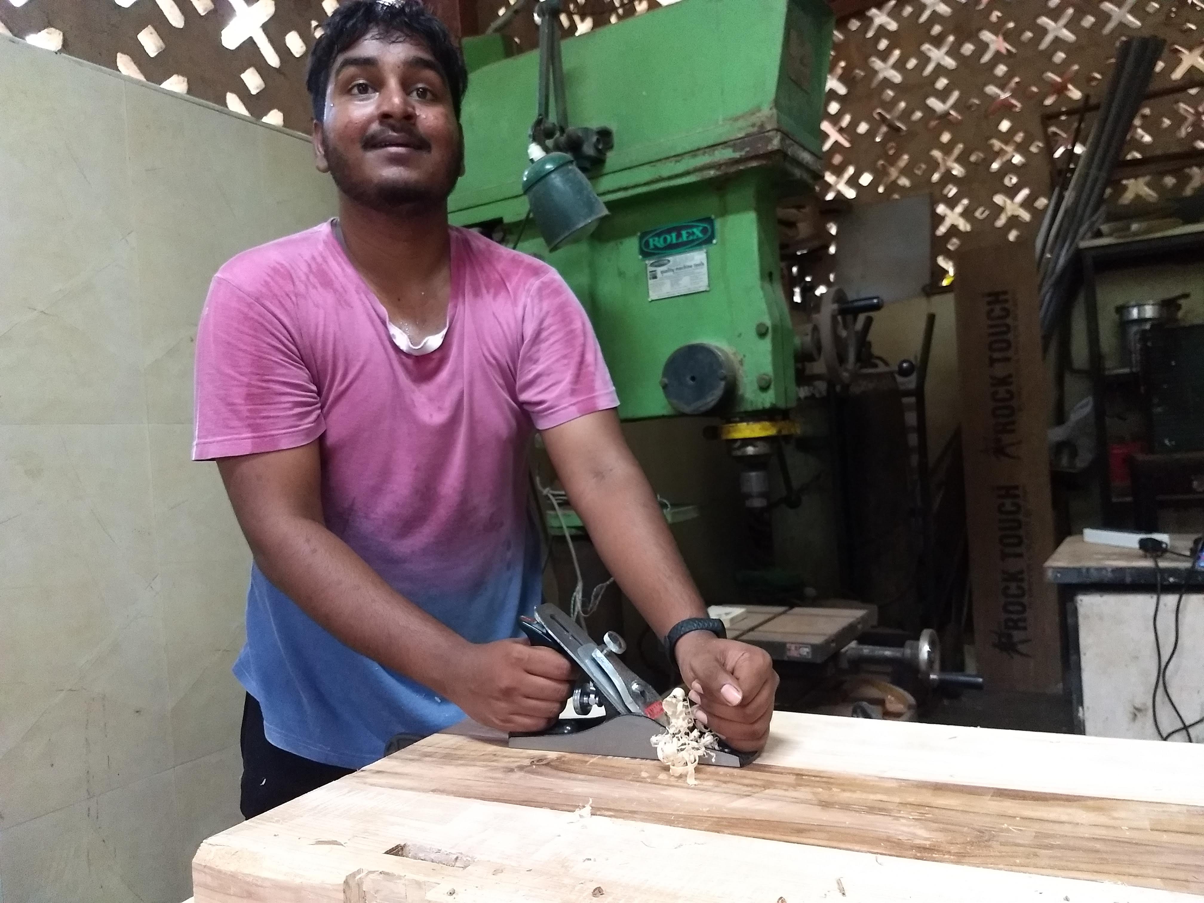
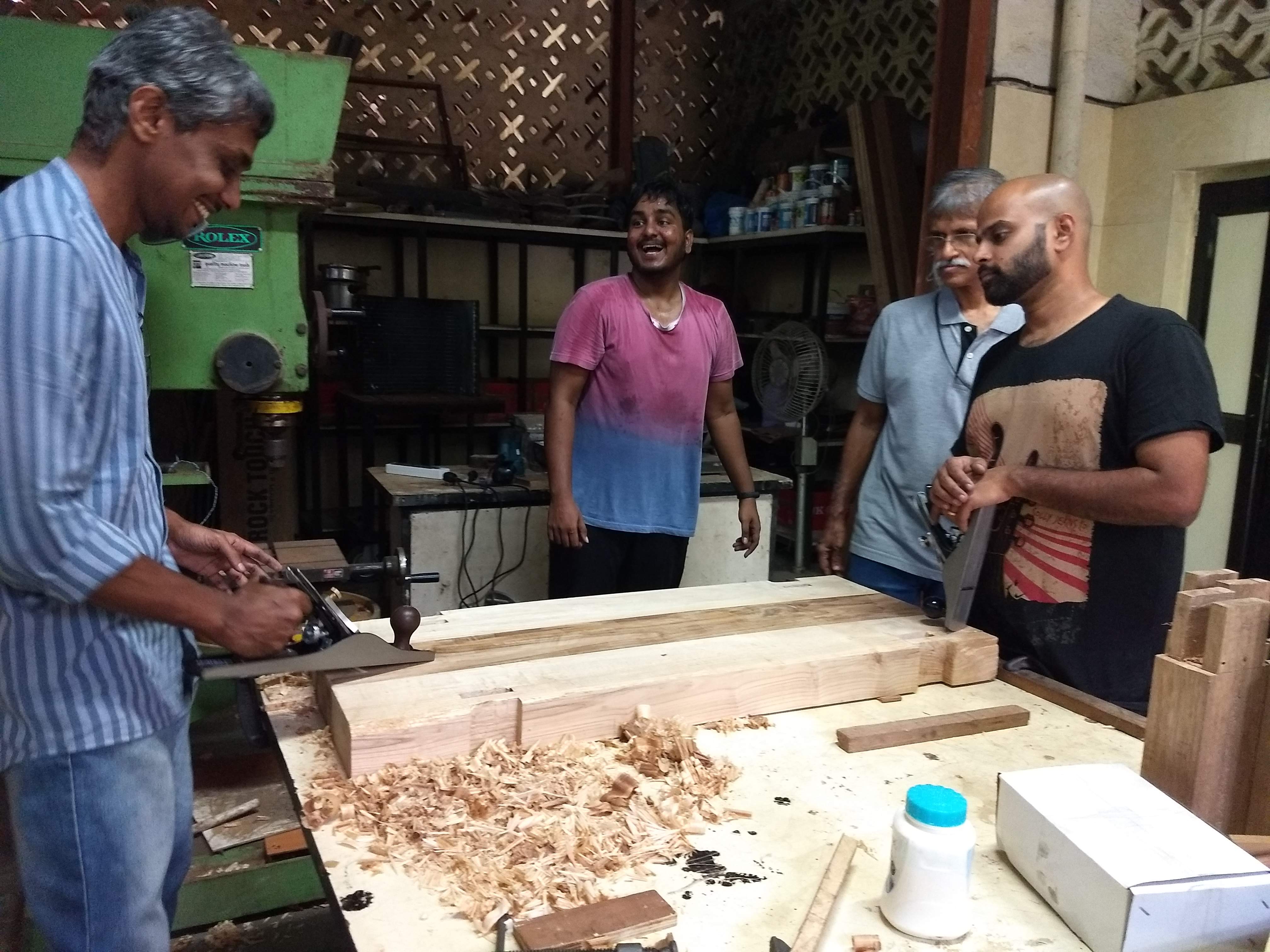
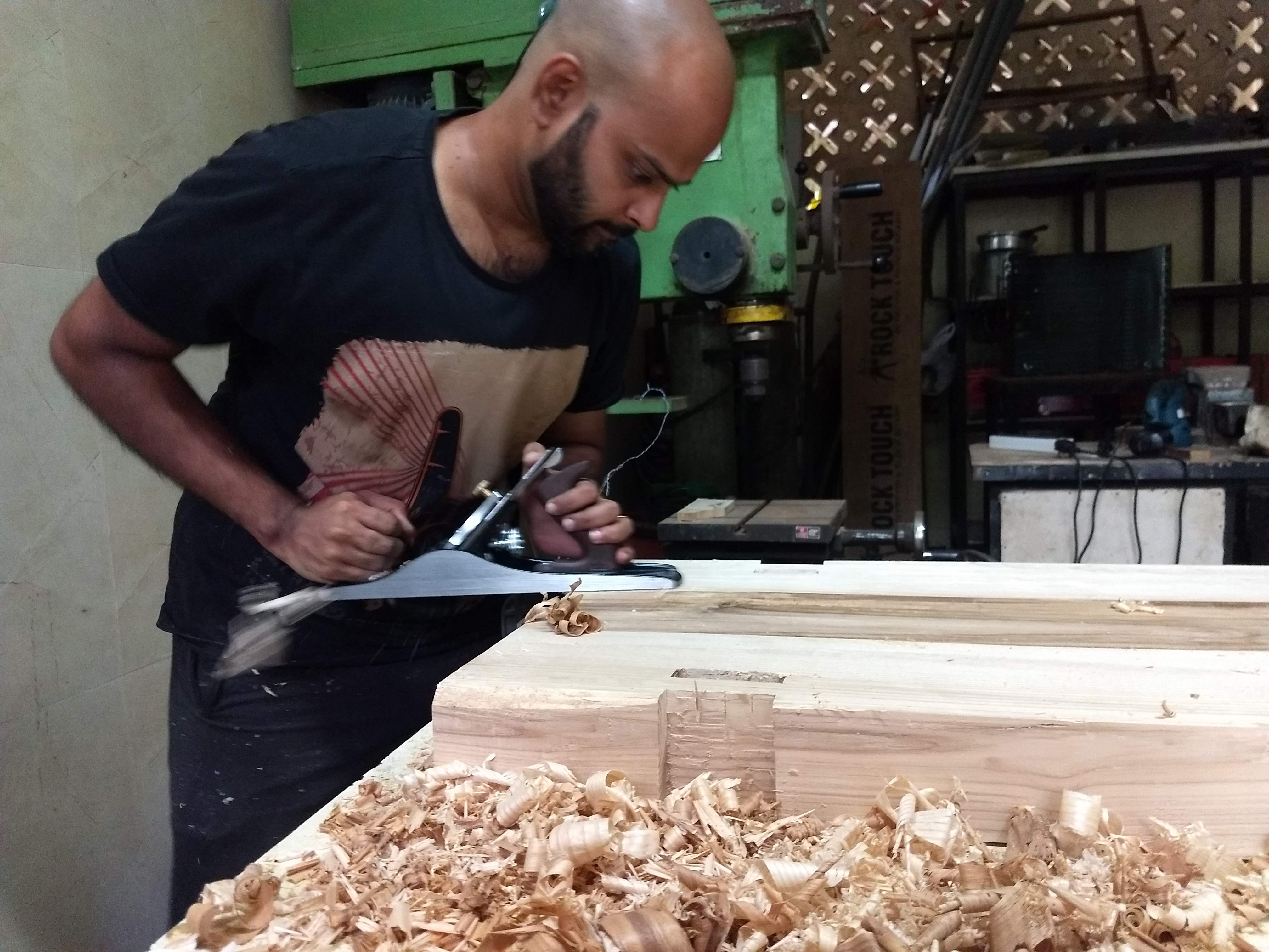
We started the day to plane the legs of the wood. @VirenVaz got his own planer today. Its indeed a fascinating tool which comes in various shapes, sizes and forms.
Balancing is most important when you want to target a certain section of wood area which you are planeing. The spacing and positioning of the front and back leg, the way you hold the tool and the body movements are all very important factor while using this.
There can be risk of injury and the job will be don poorly when the form is not correct.
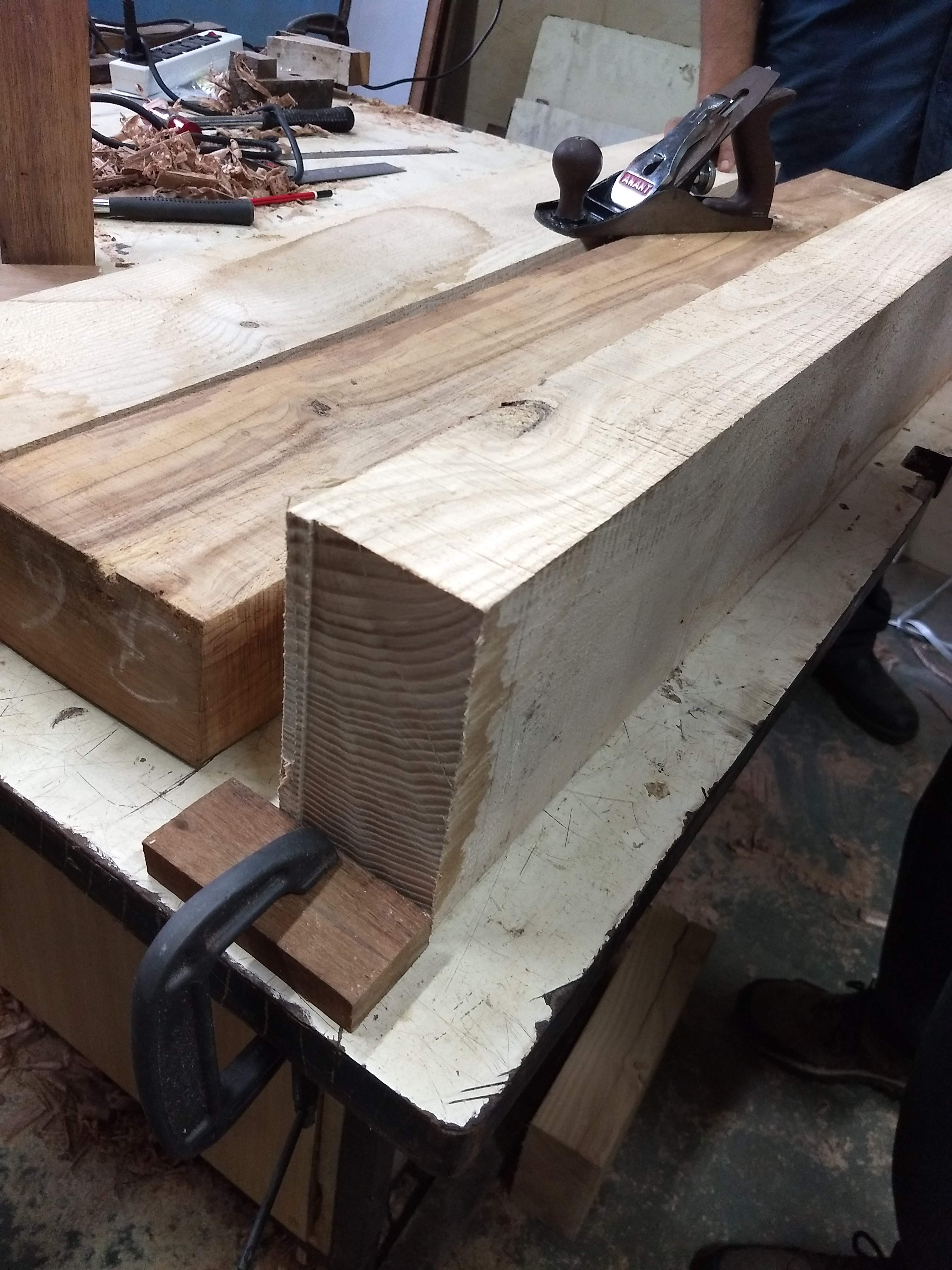
Thereafter, we clamped it to make the necessary cut.
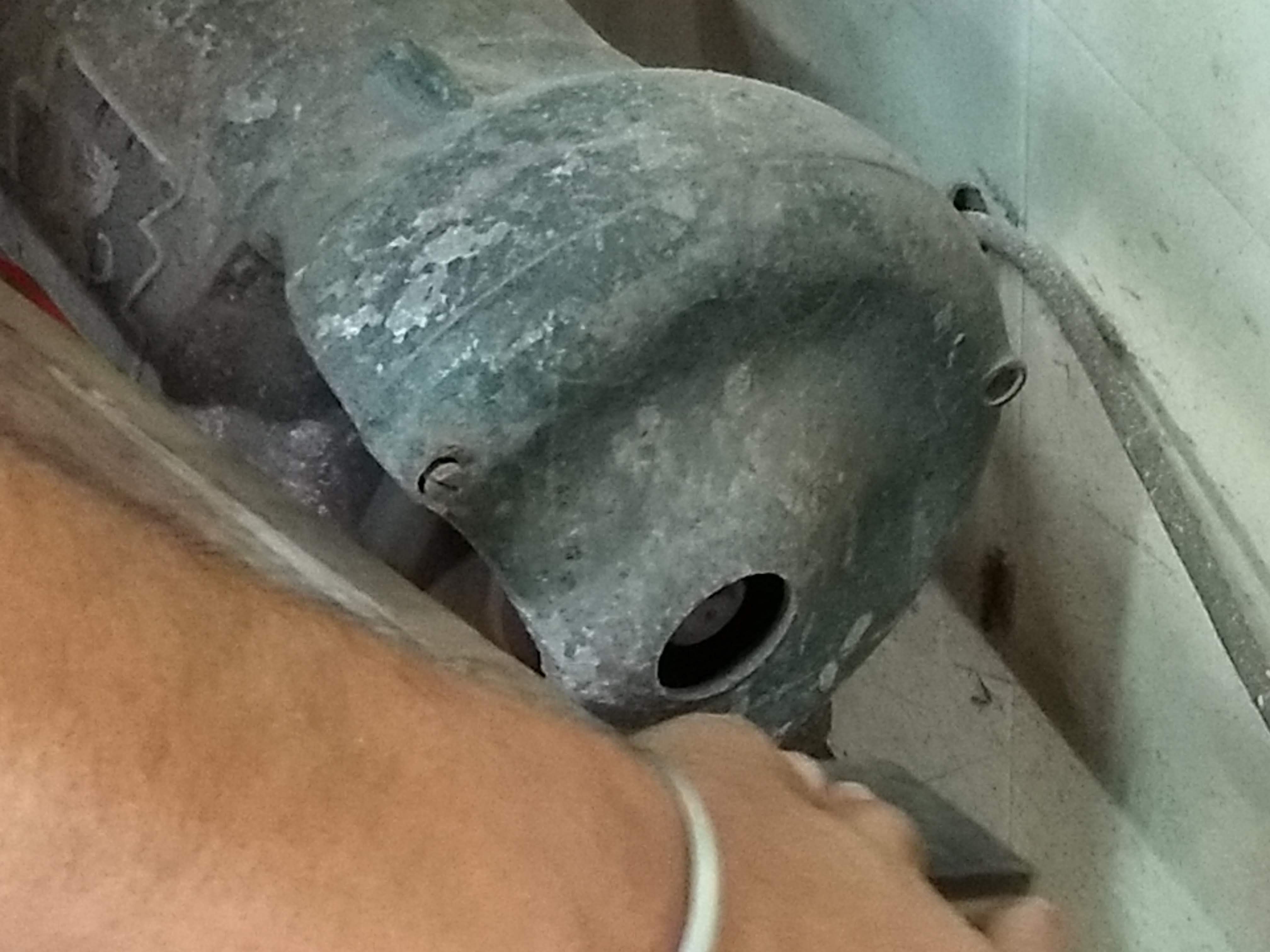
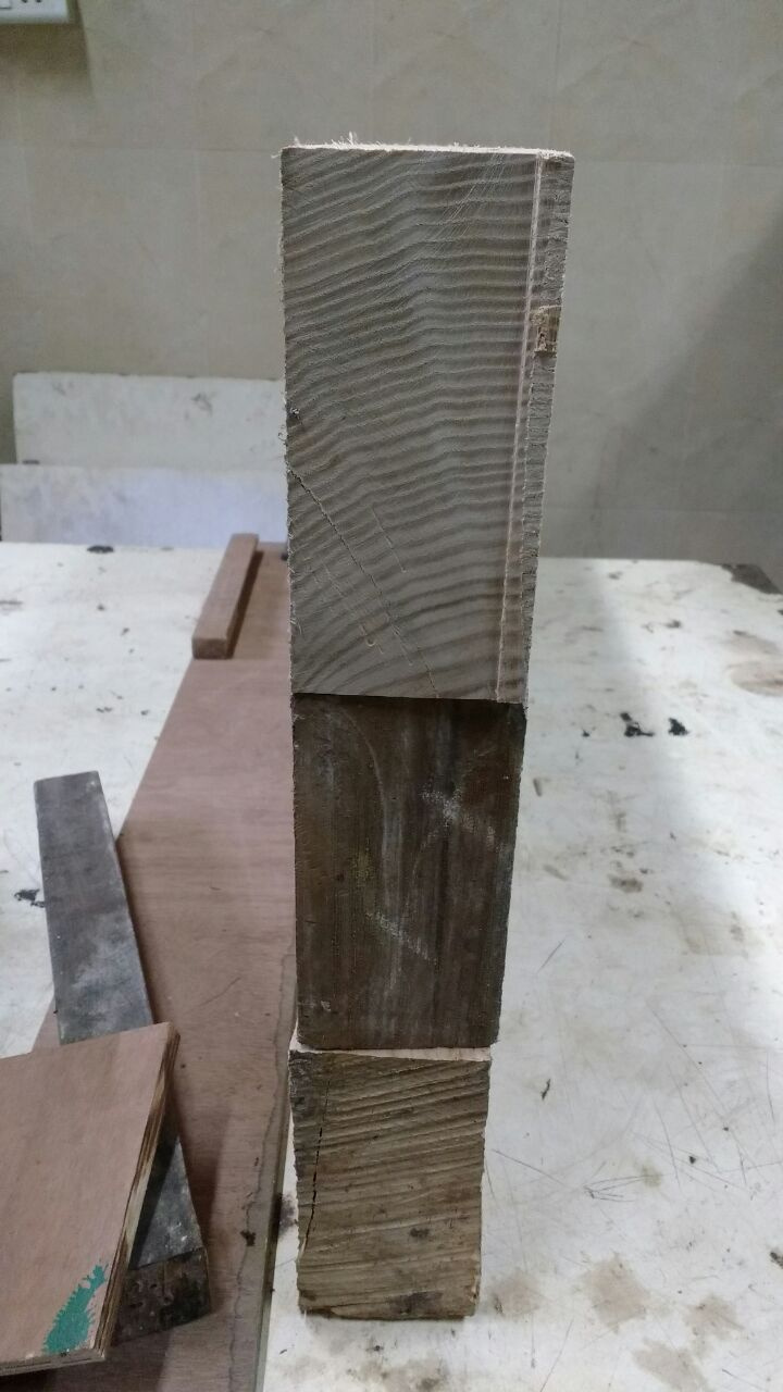
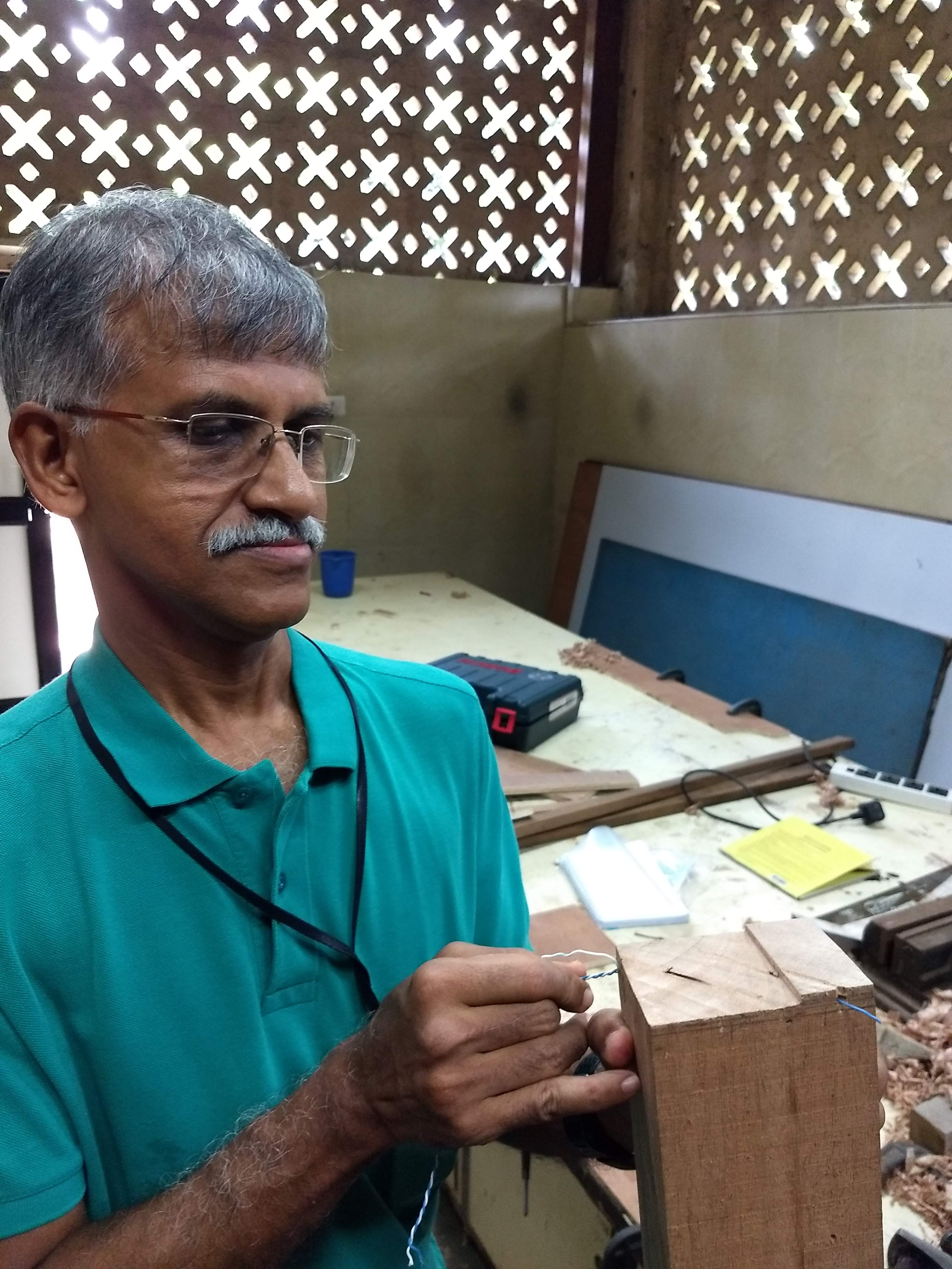
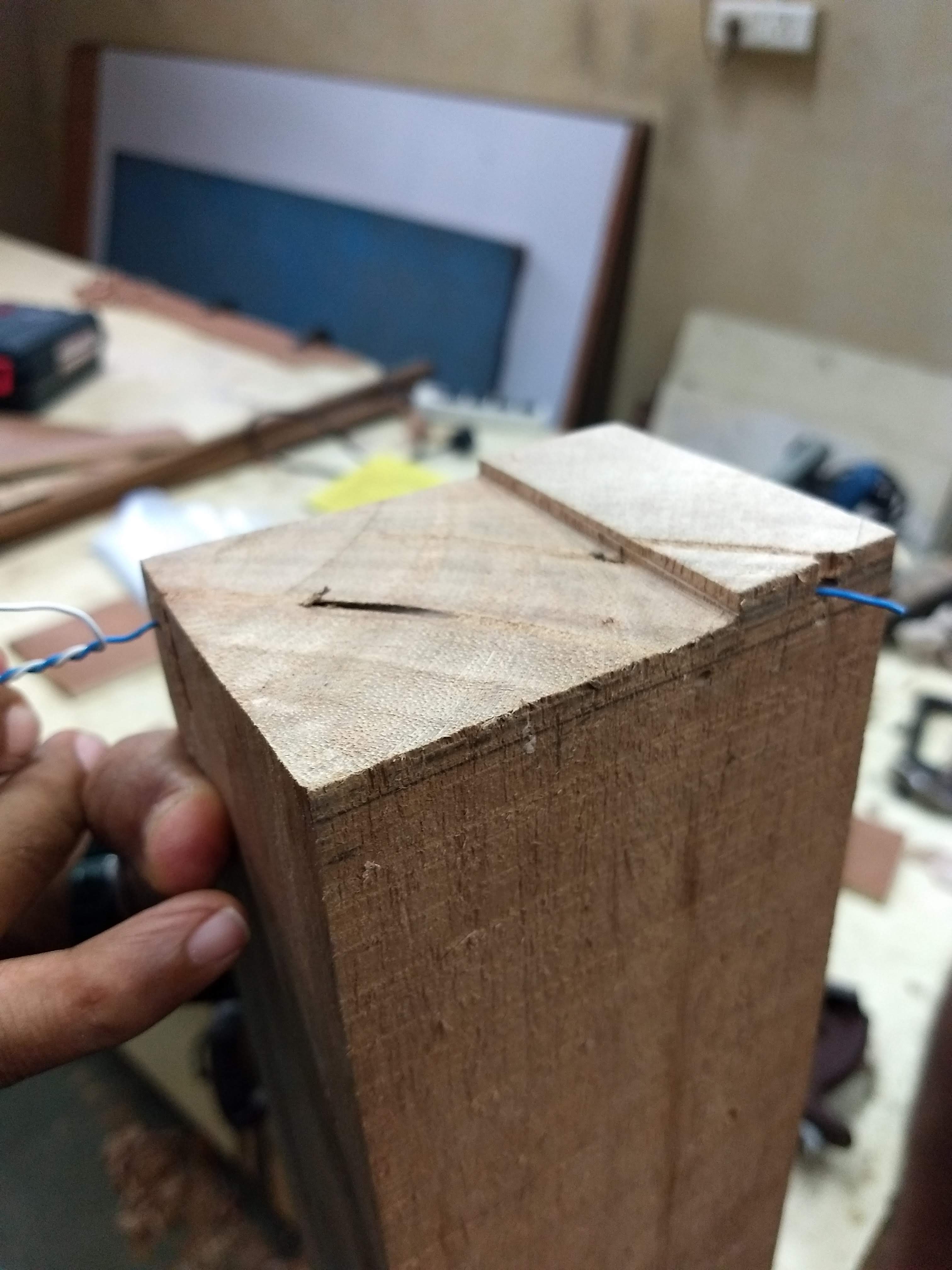
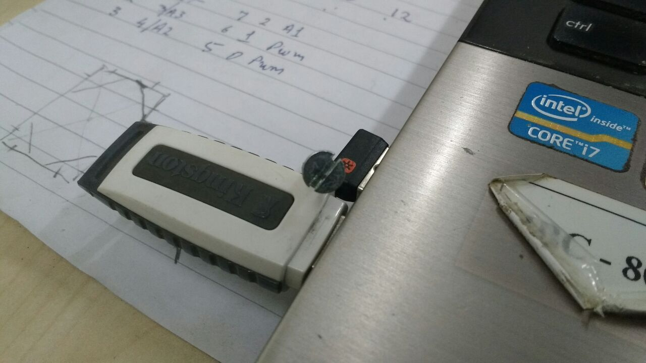
Meanwhile, @jtd discovered a hole inside one the wooden pieces and we were surprised to see the depth of it. Here you can see the wire coming out from the other end.
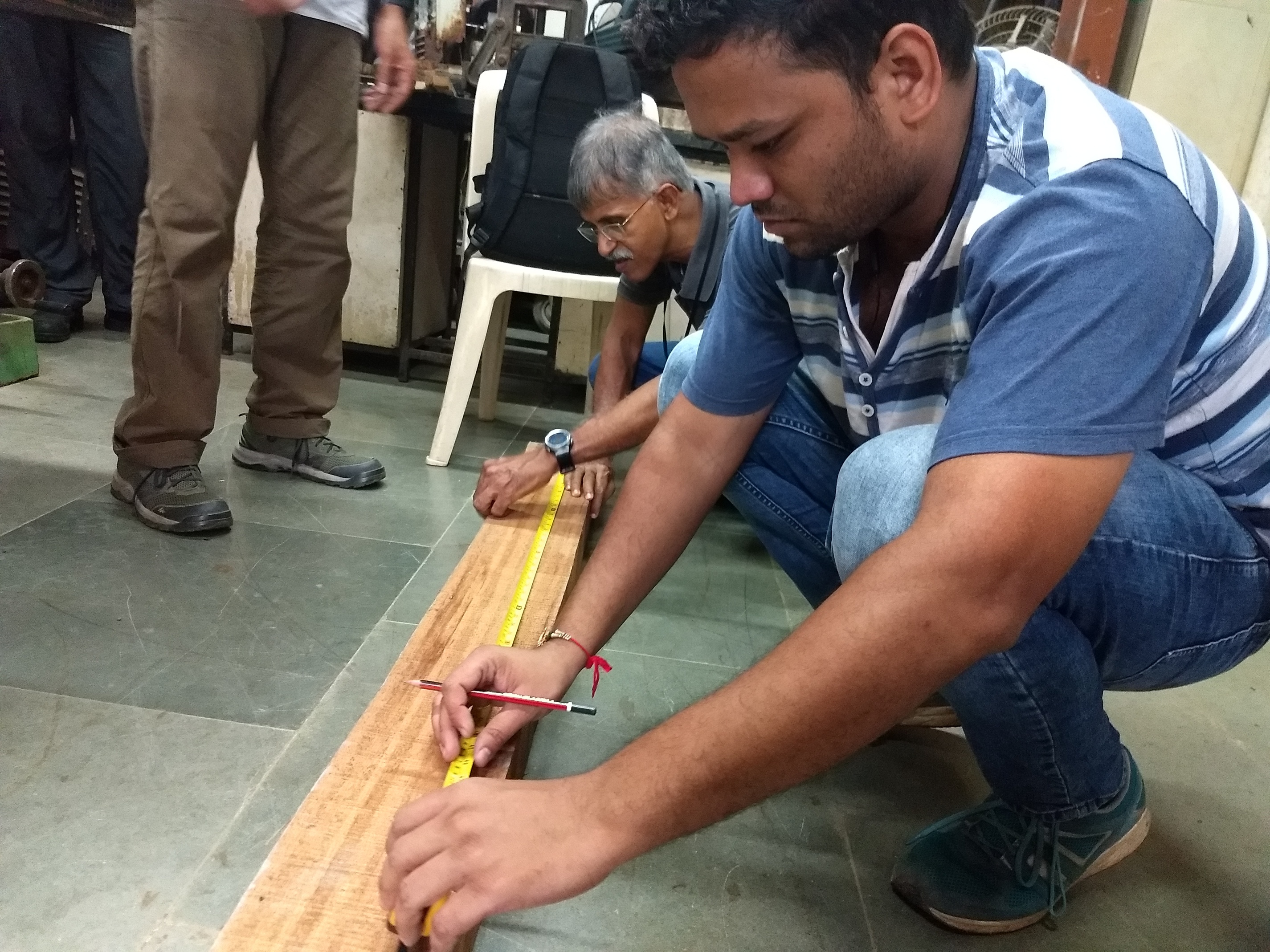
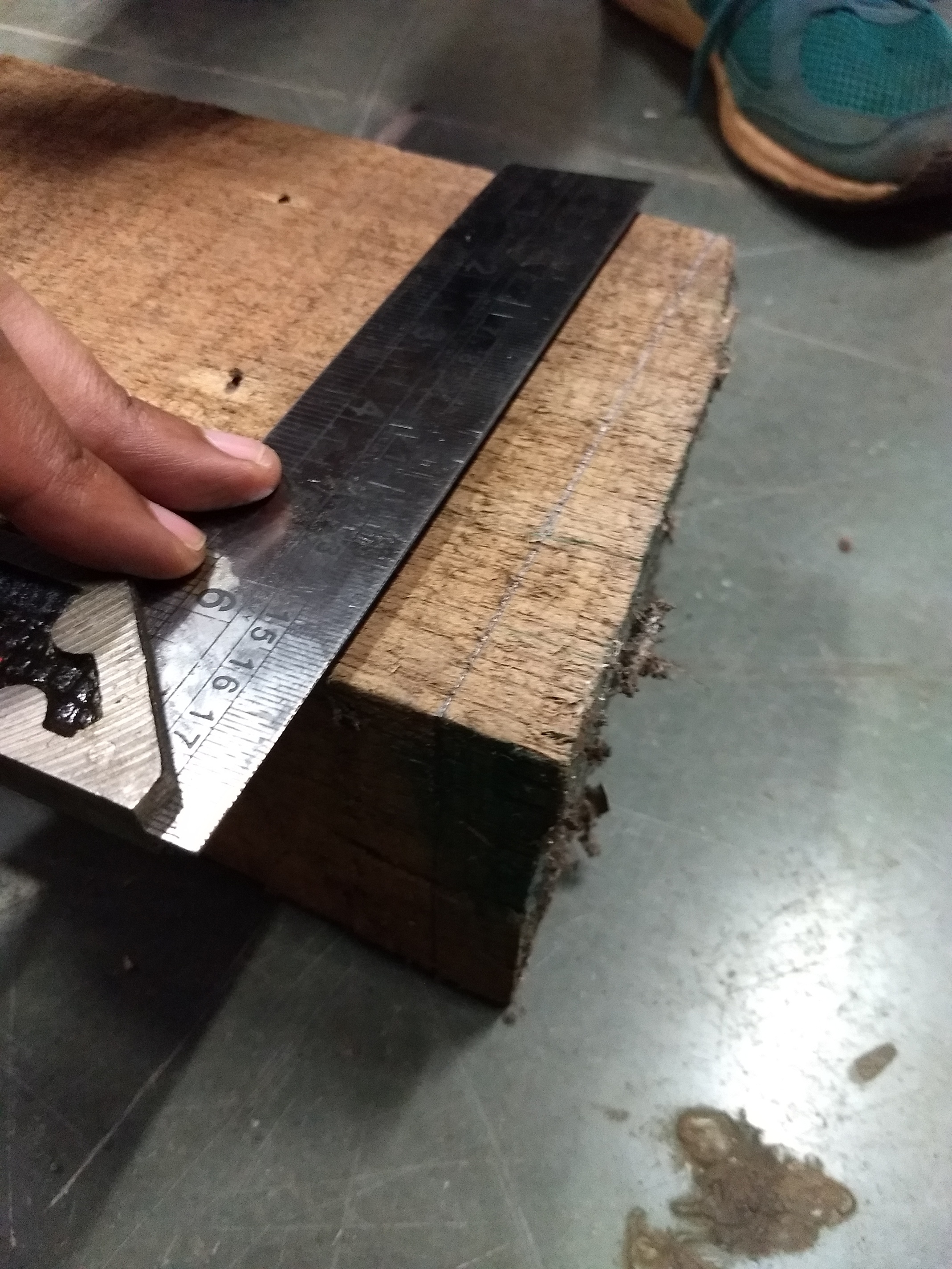
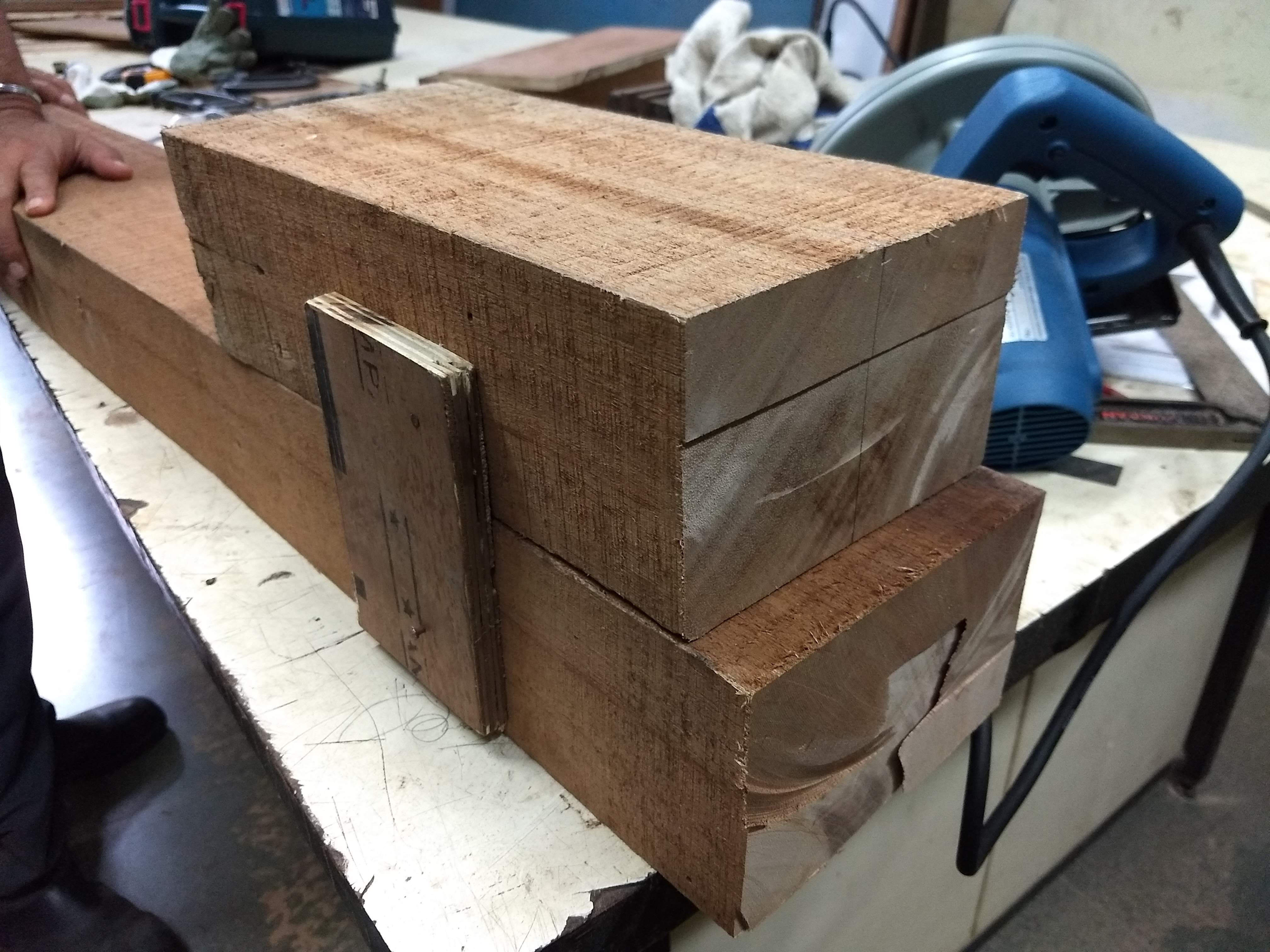
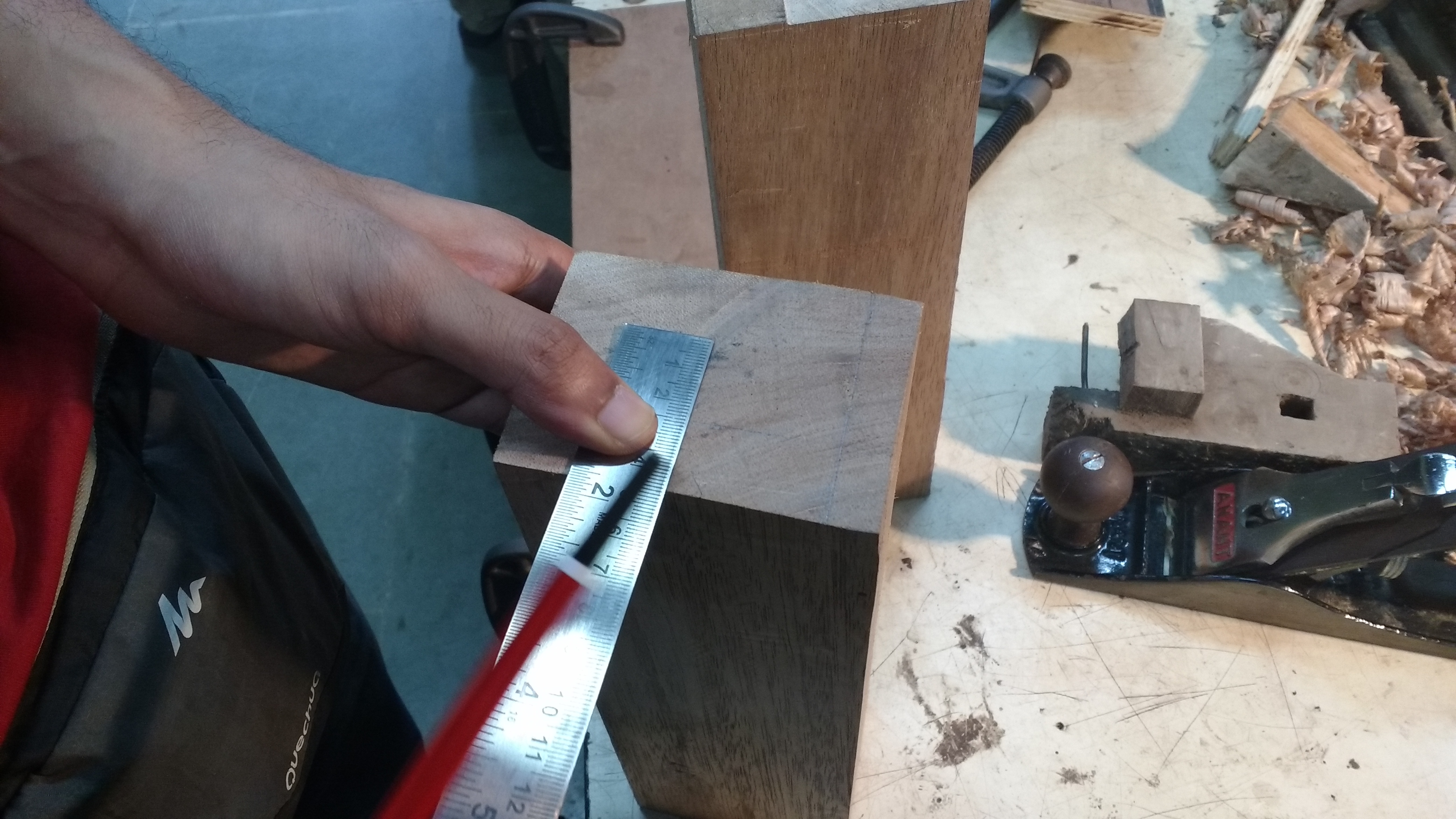
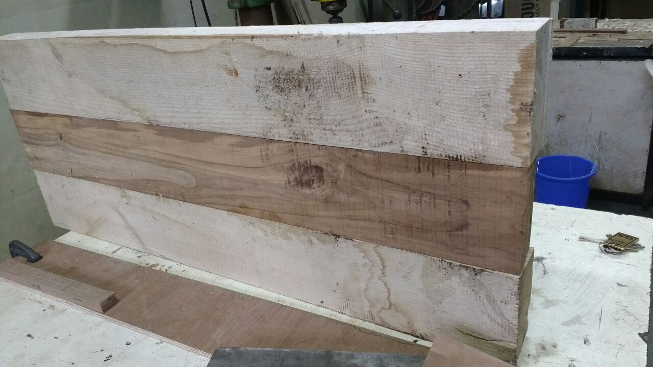
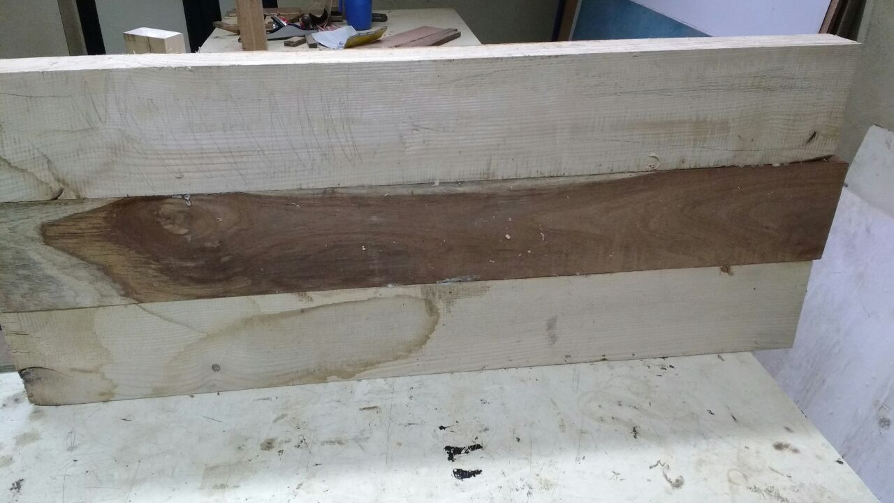
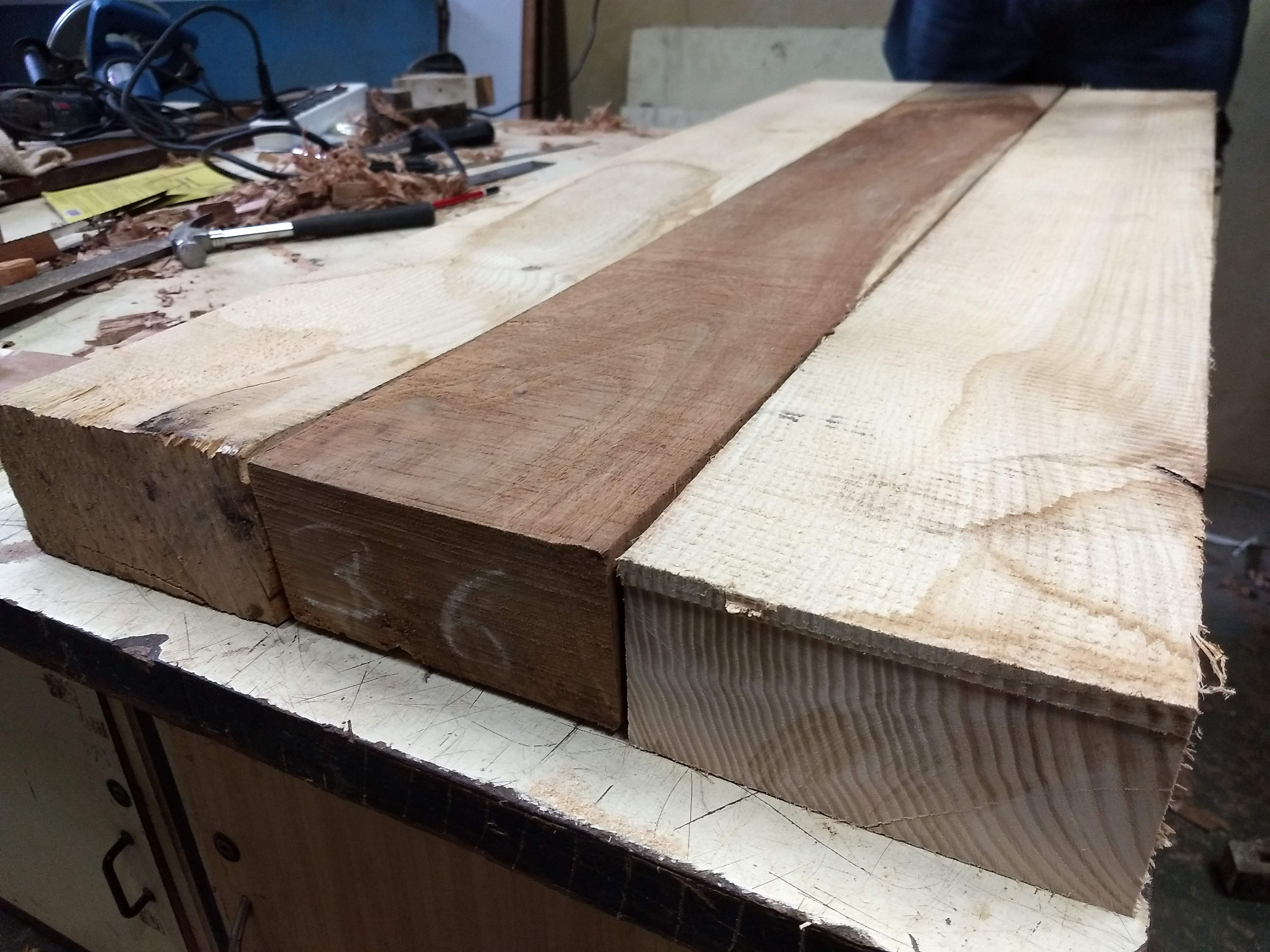
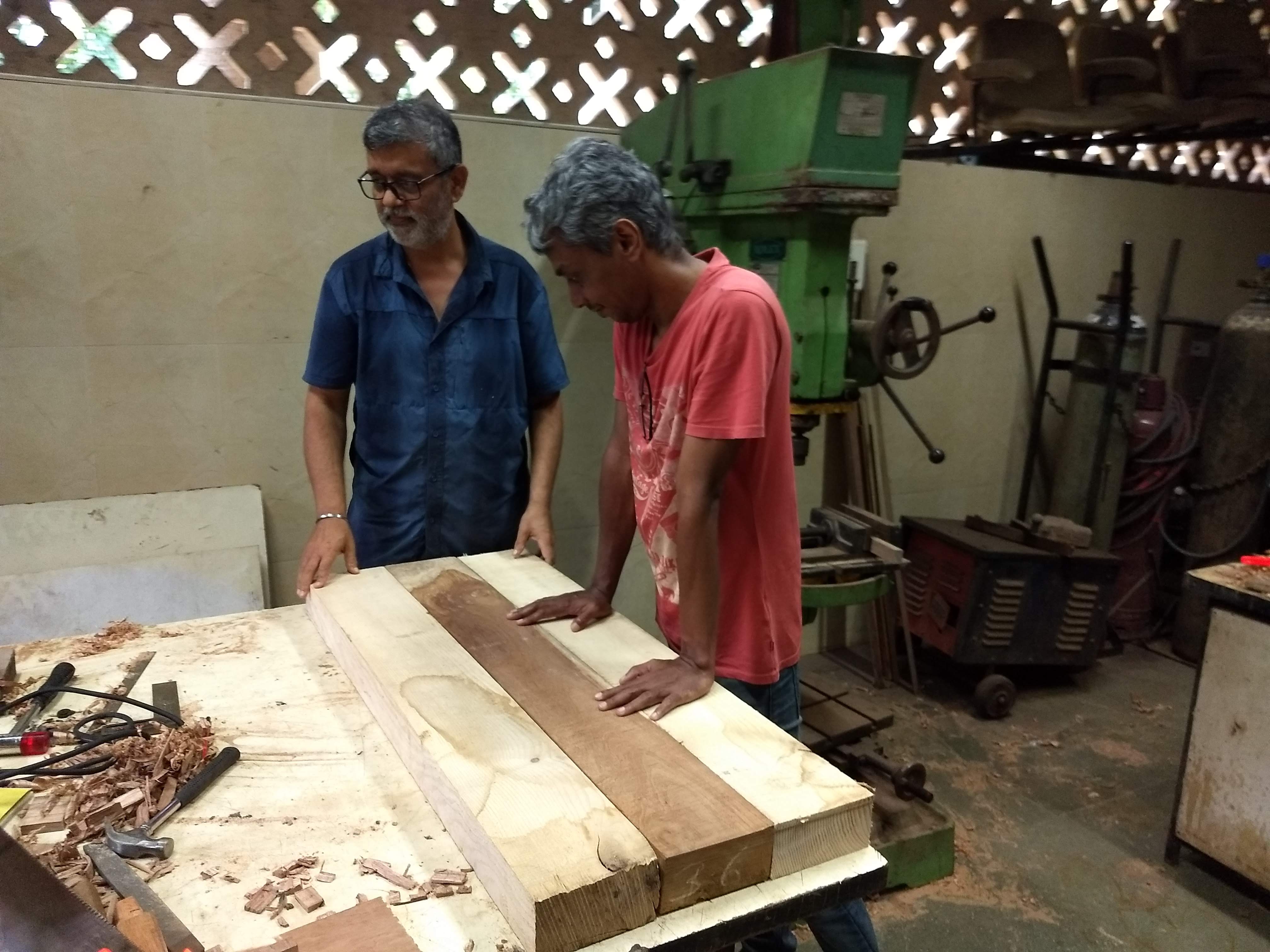
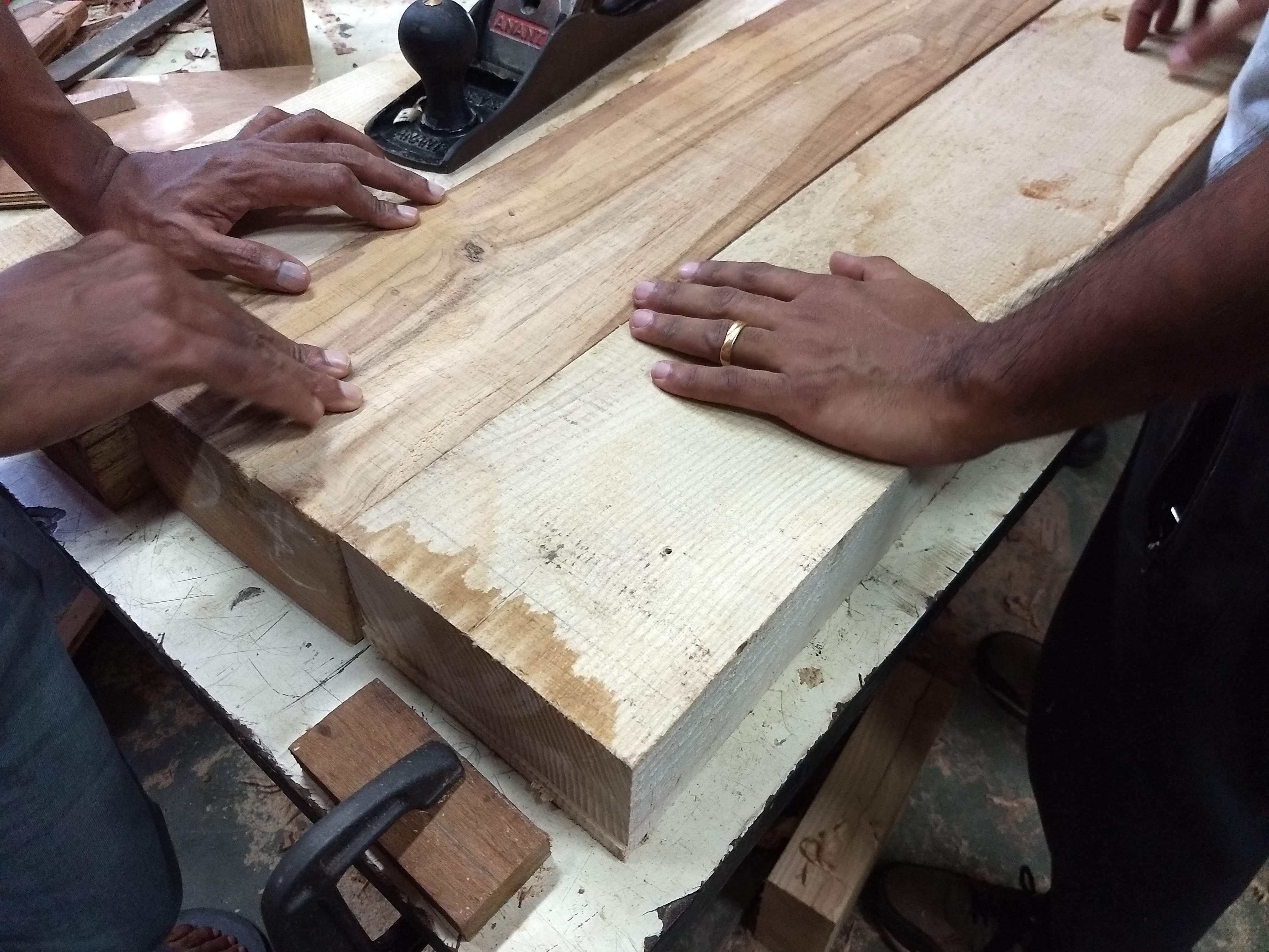
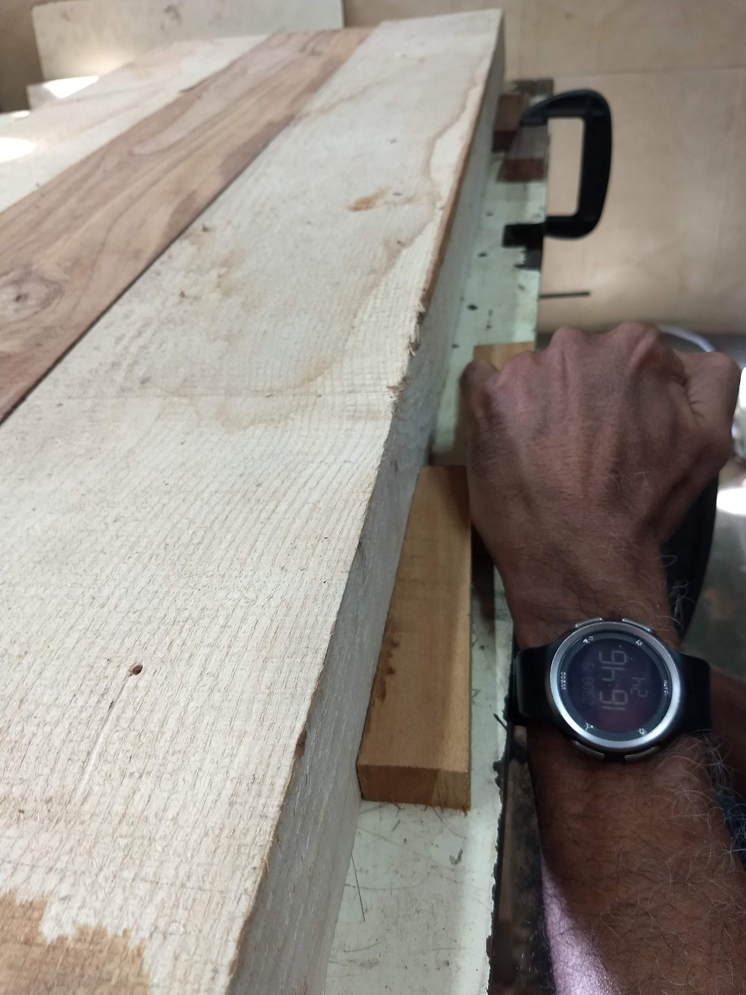
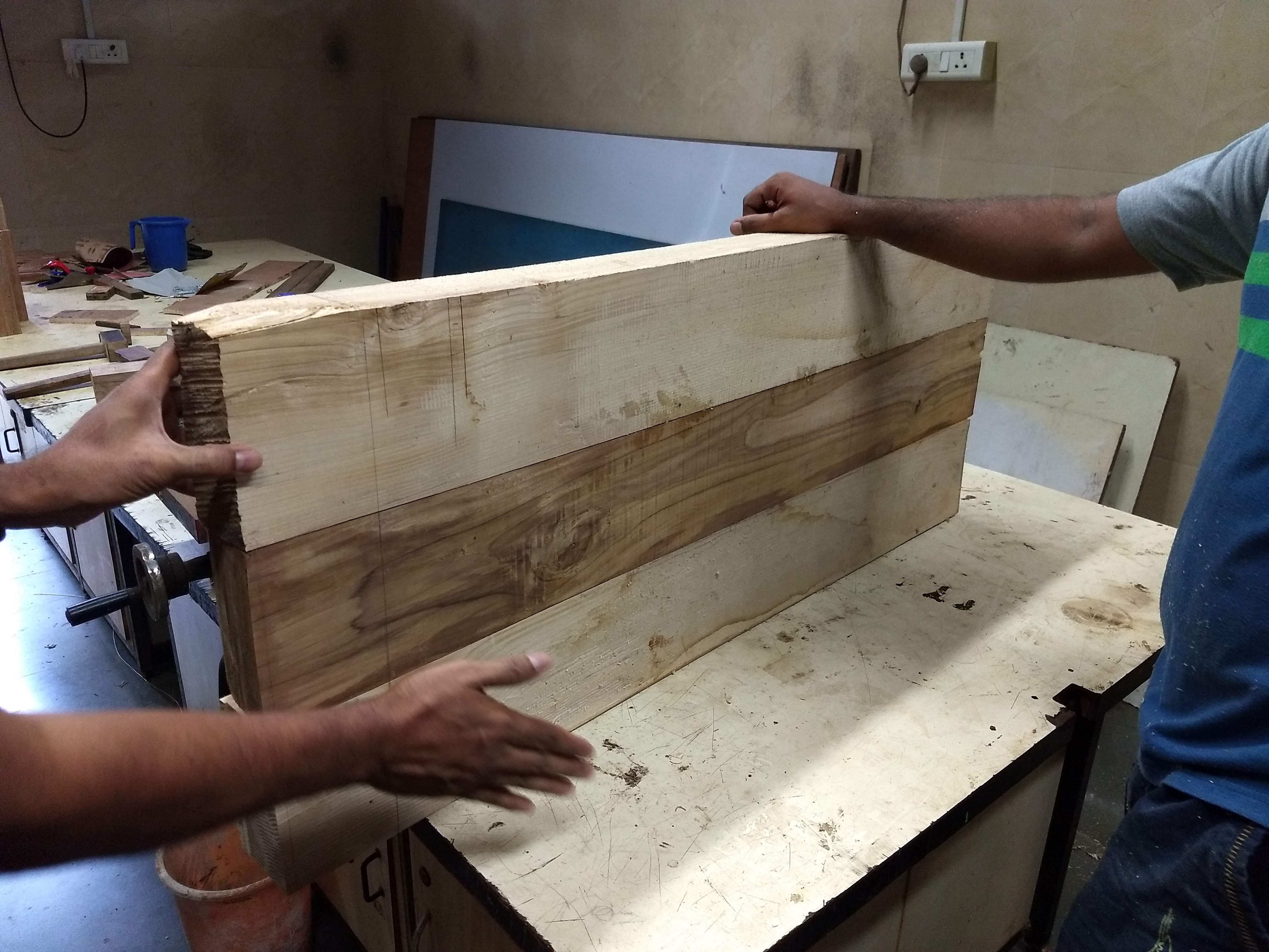
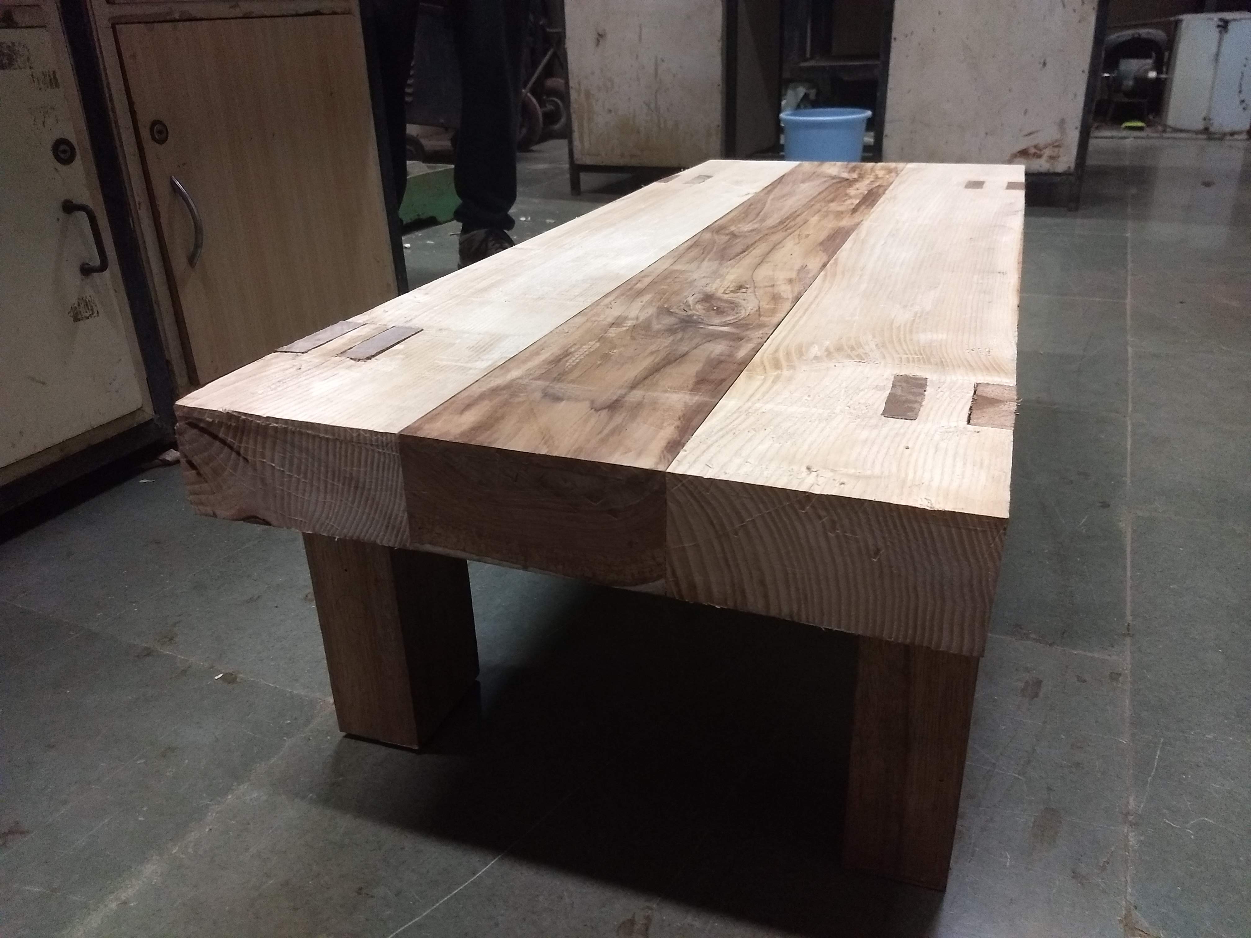
The wood arrived in the afternoon. We split the longer one into 4 ft each. We got two different colors and sandwich the logs to give an aesthetically pleasing texture.
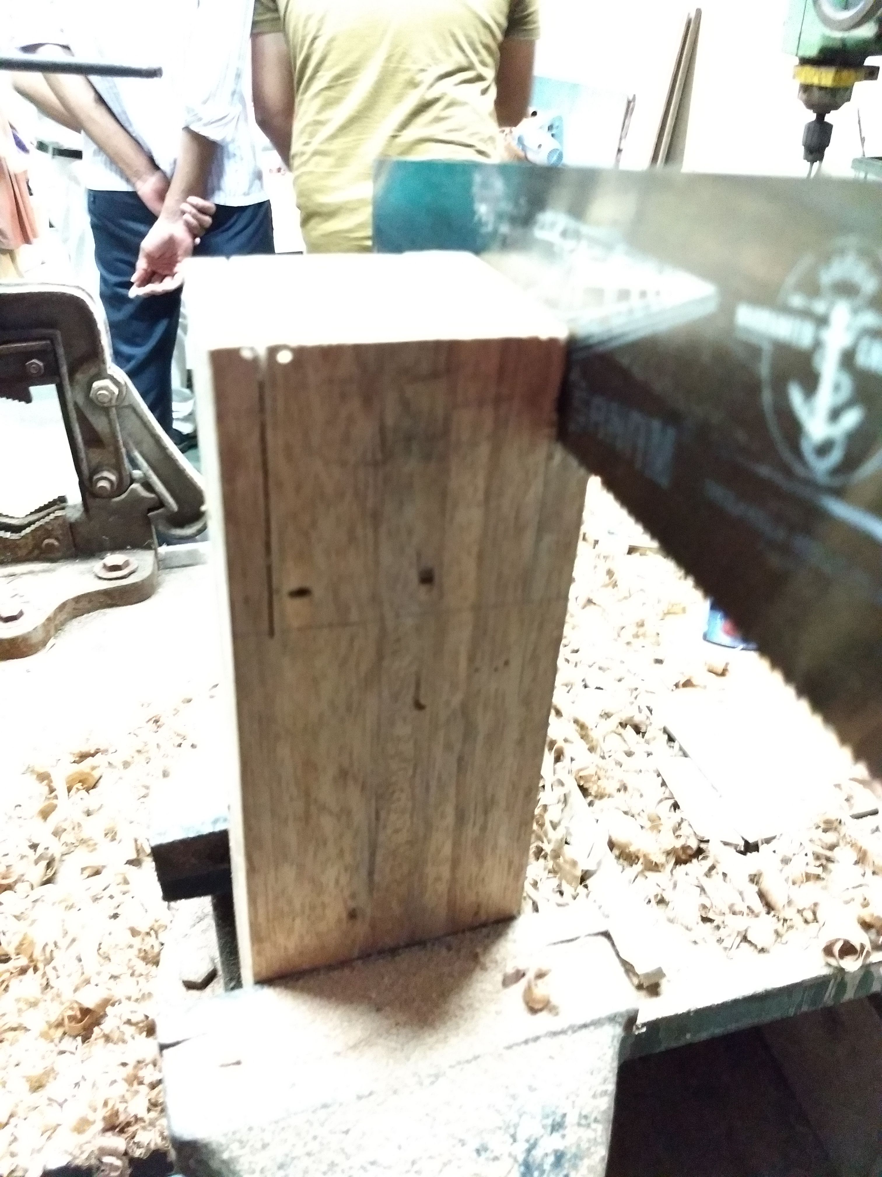
Circular saw and hand saw were used to get the desired length after the measurements.
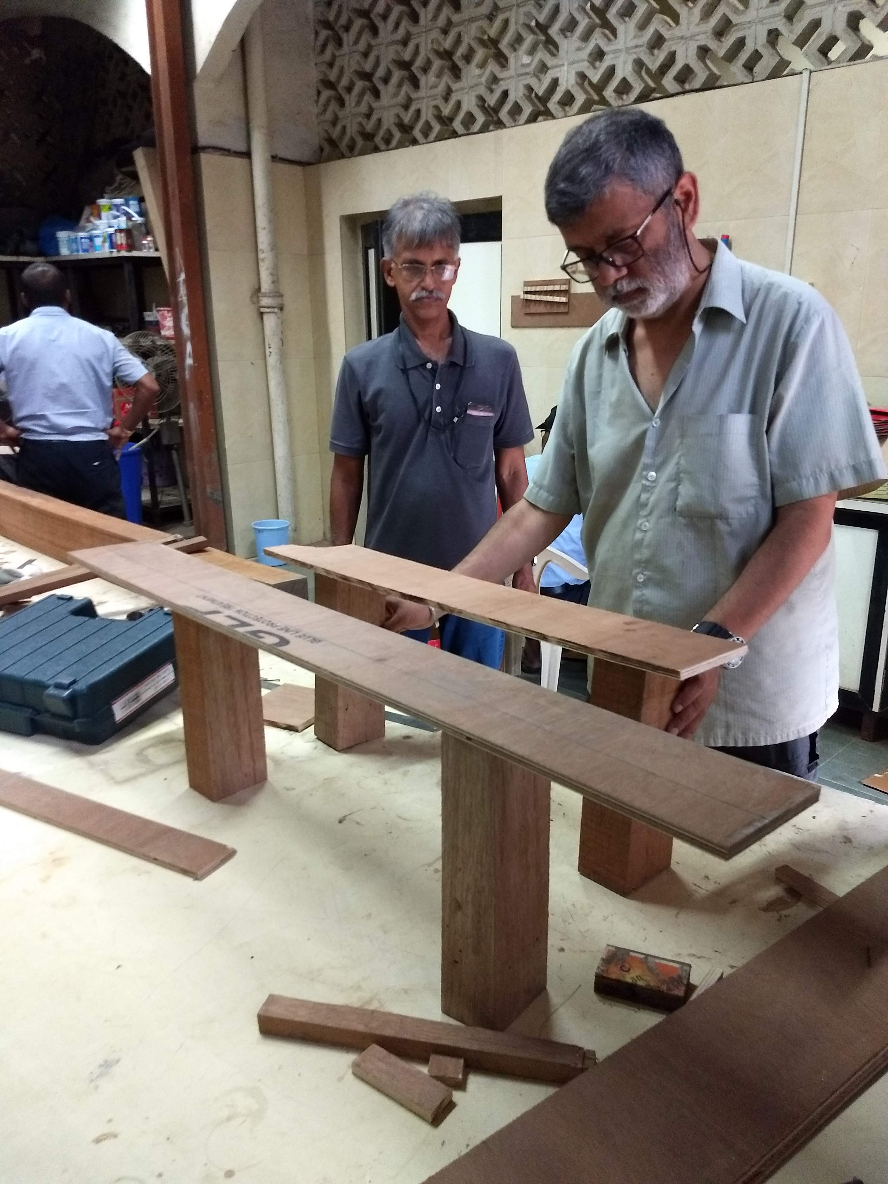
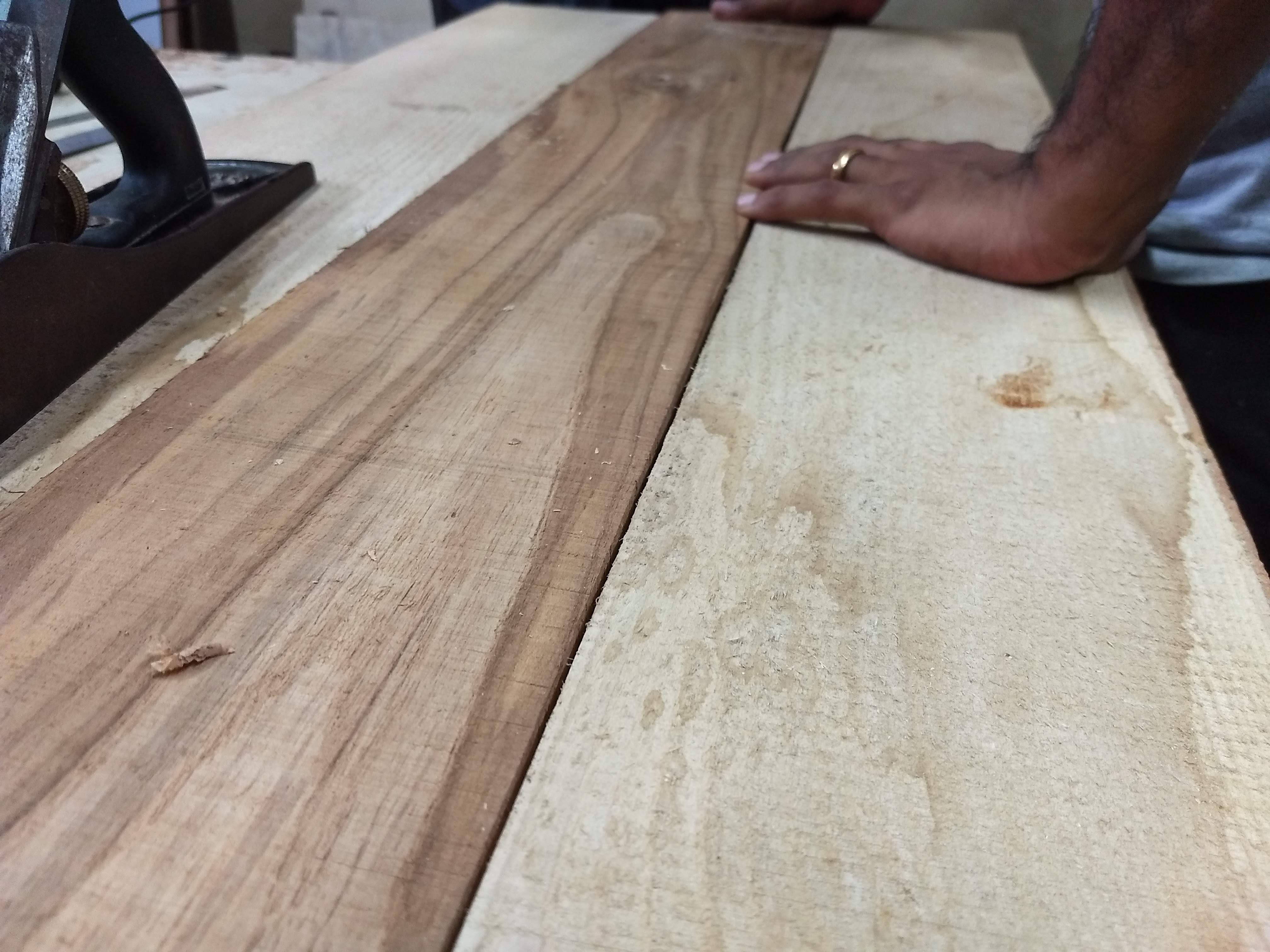
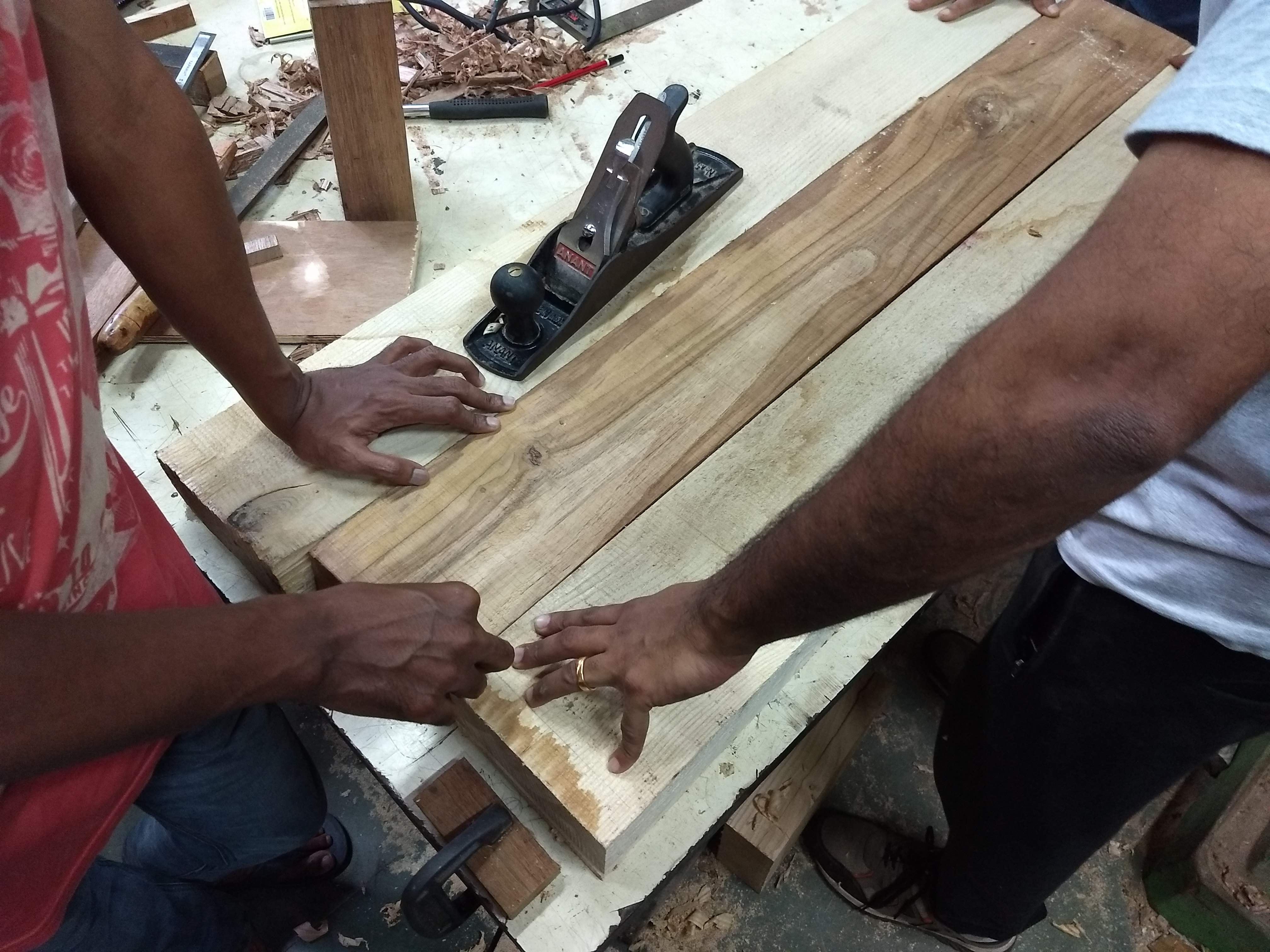
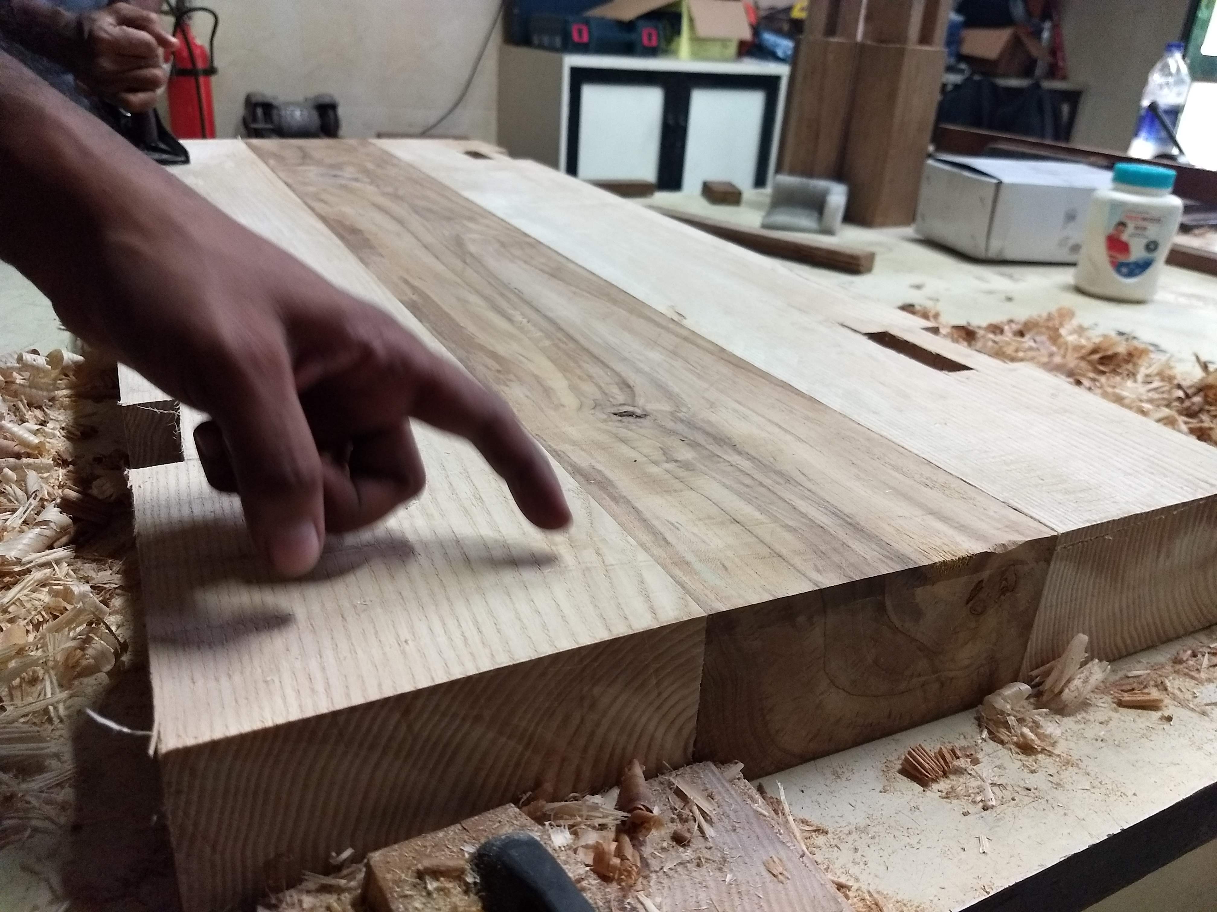
As you can see above, the logs are ready to be glued. Not really, on placing it side by side, there are gaps which need to be fixed so that the adhesive can be applied effectively.
For ensuring that, we need to plane the specific region from the side and repeat the process iteratively.
Finally, after a lot of iterations, we finished the planeing. Then we applied adhesive on sides.
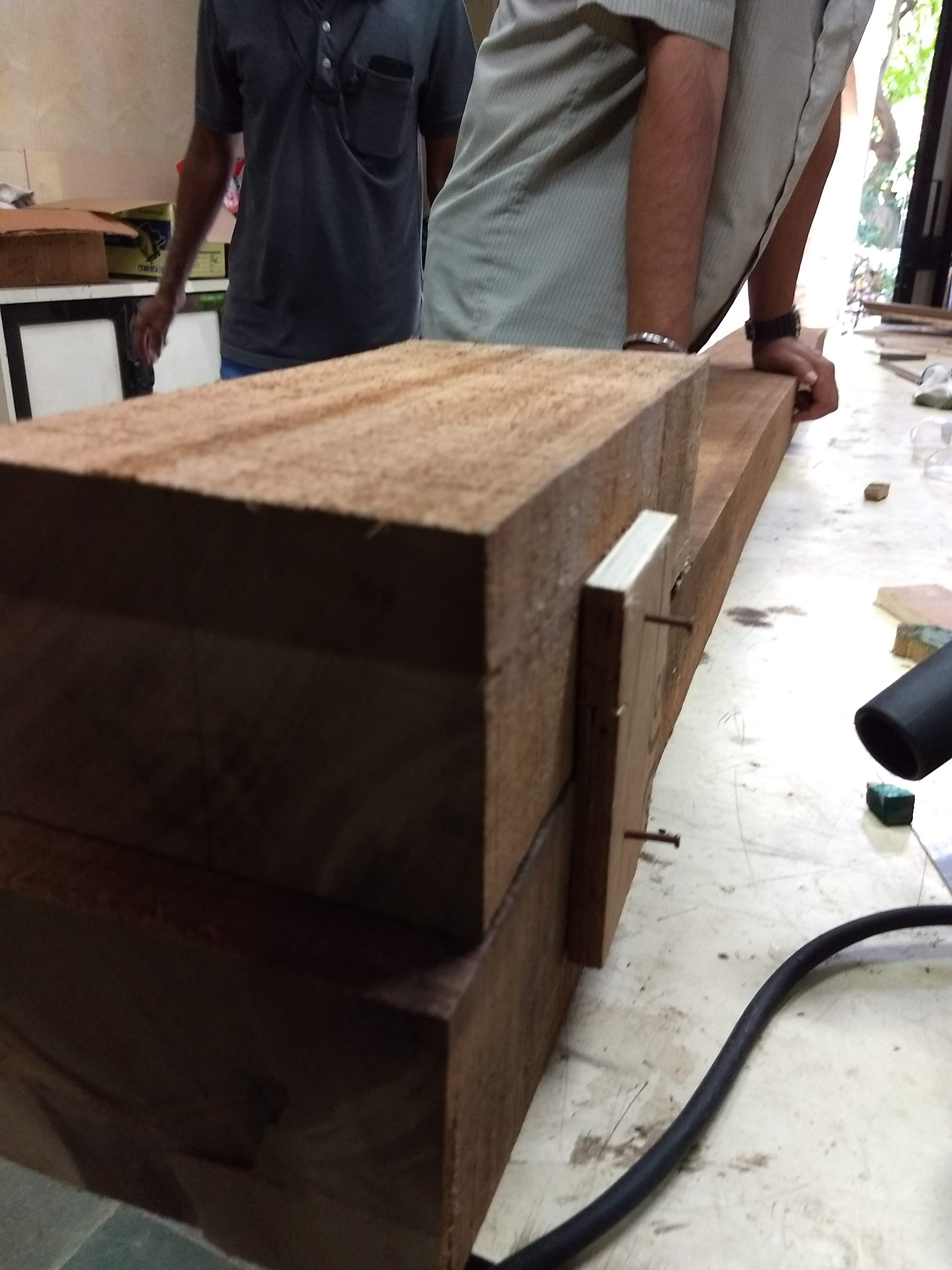
Here I would like to mention about an interesting detour. @jtd and @VirenVaz were also working on a mechanism which can hold the big wooden pieces together. One way to go about it to have a big clamp to hold these things, but we don’t have that here. The other interesting frugal technique is to use the wedge mechanism to make a clamp.
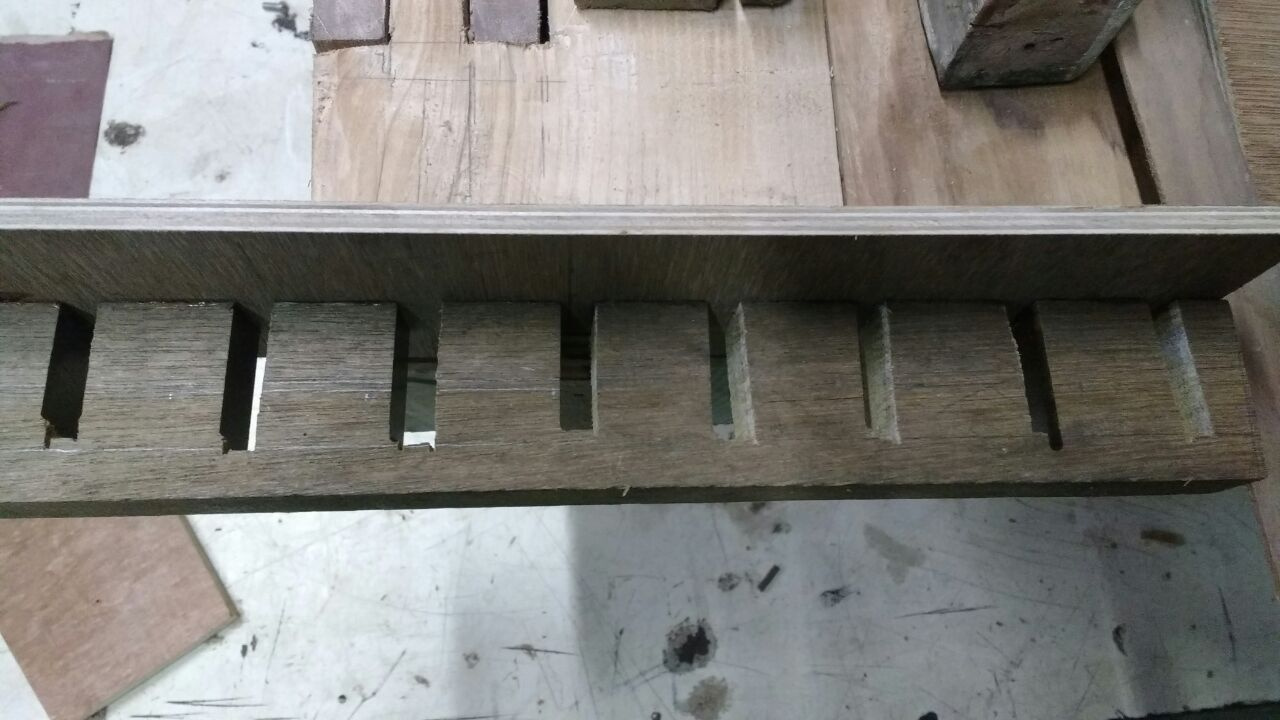
The slots were cut using the huge chop saw in the workshop. I then had to widen each cut. I used the chisel initially, and ended up with one side cracking off the piece. A brass nail and wood glue set it right. I then switched to the 18" hand saw to expand the slots.
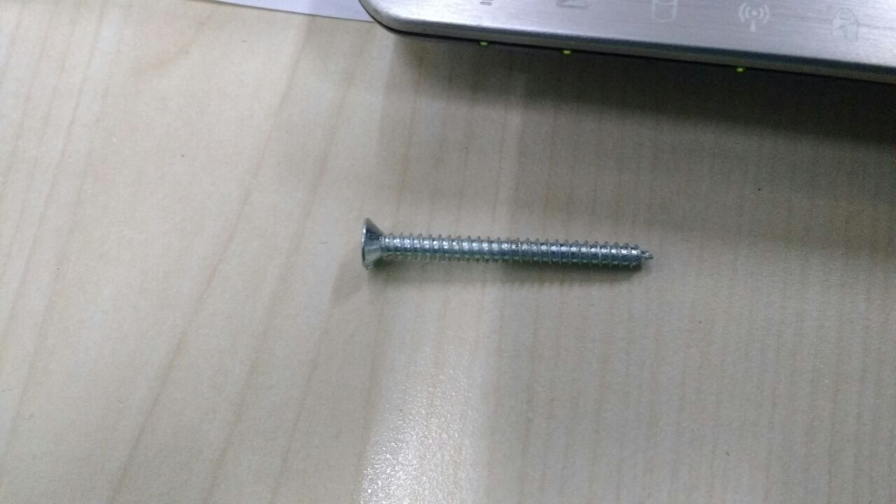
To fix the slotted piece to the rear cleat piece I used two self threading metal CSK minus head screws type AB thread, length 1.5".
A minus head screw has a single slot to hold the screw driver bit and requires one to maintain a plumb vertical position while driving the screw. Consequently one has to exert substantial down wards pressure to prevent the screwdriver from jumping out and shredding the head. I used the power drill machine with a minus bit to ease the job. Unfortunately in an attempt to make the head flush with the ply I over torqued the screw and caused it to snap. Extracting a broken screw from wood is an onerous task. So I had to drill a fresh set of holes. I changed plans and instead of screws, used nails and stuck the two pieces together using poly vinyl acetate glue, more popularly known as Fevicol.
Note for self: Buy a battery powered driver and use + head screws (also known as philips head).
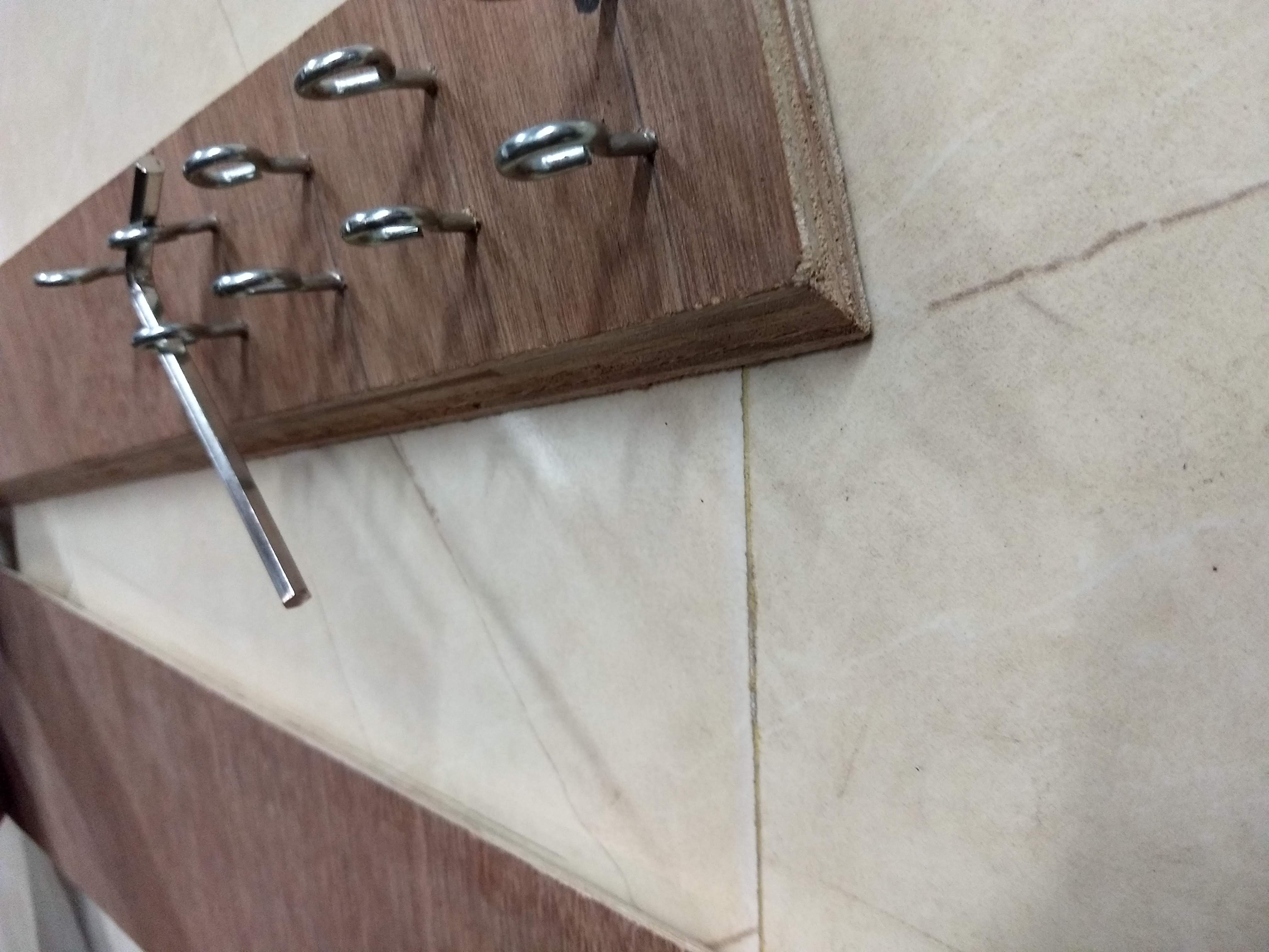
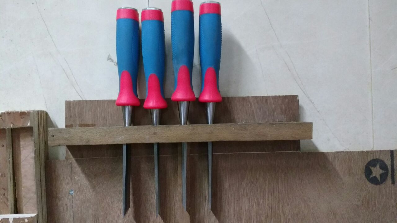
Since the holder is overhanging, the weight of the chisels will pull the stand down, but also forward. It is possible that the stand will topple, a very dangerous situation with sharp edged and heavy objects. I therefore added a small piece of wood that acts as a clamp, preventing any possibility of toppling. I used two small 1" tack nails and PVA glue.
Thinking about the ergonomics and safety, I thought that the chisel might snag if one twists and pulls it out, thereby dislodging the entire stand and causing an accident. This would happen if one used only one hand. However I could not cause such a snag despite several attempts.
Day 4
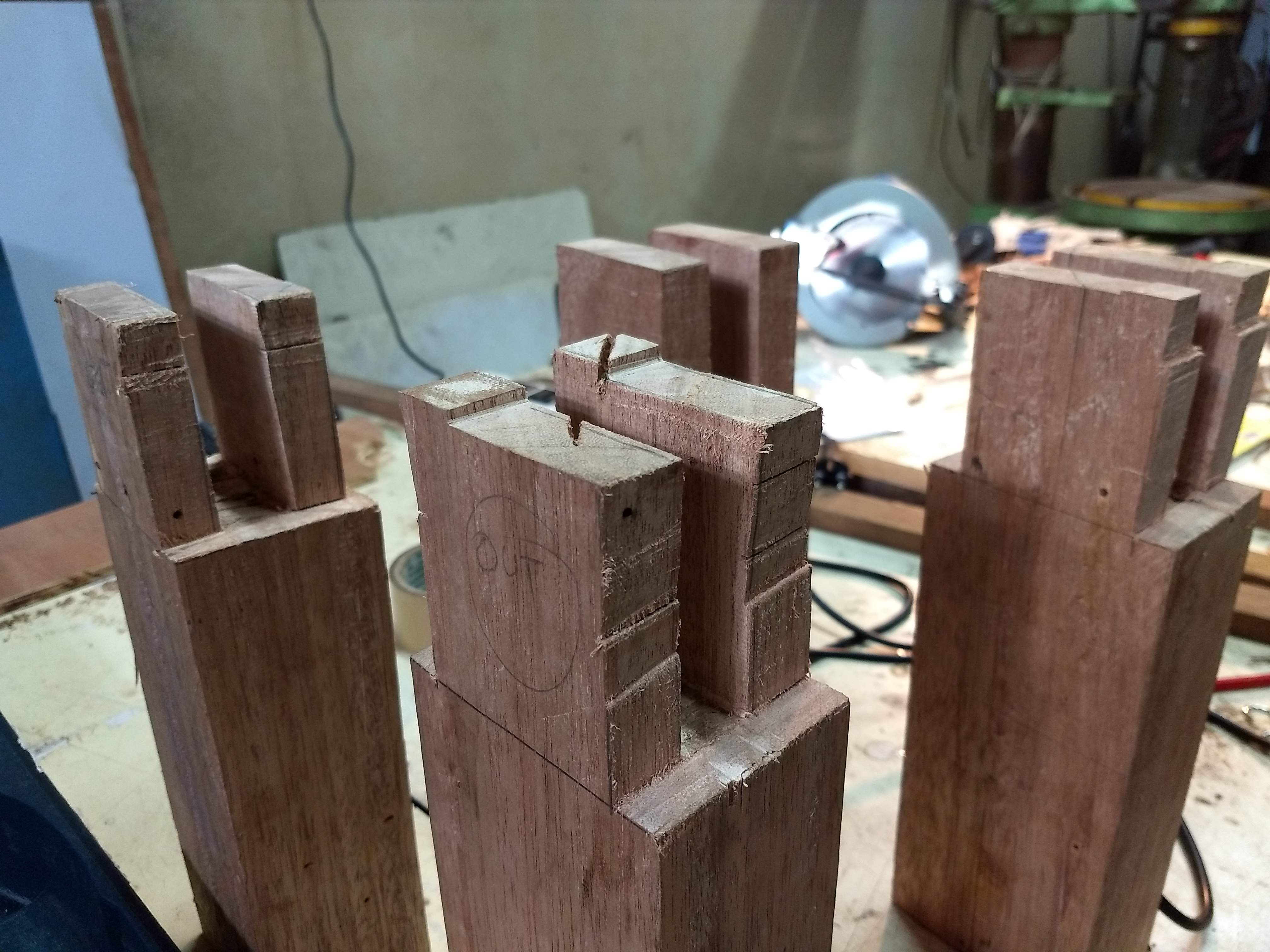
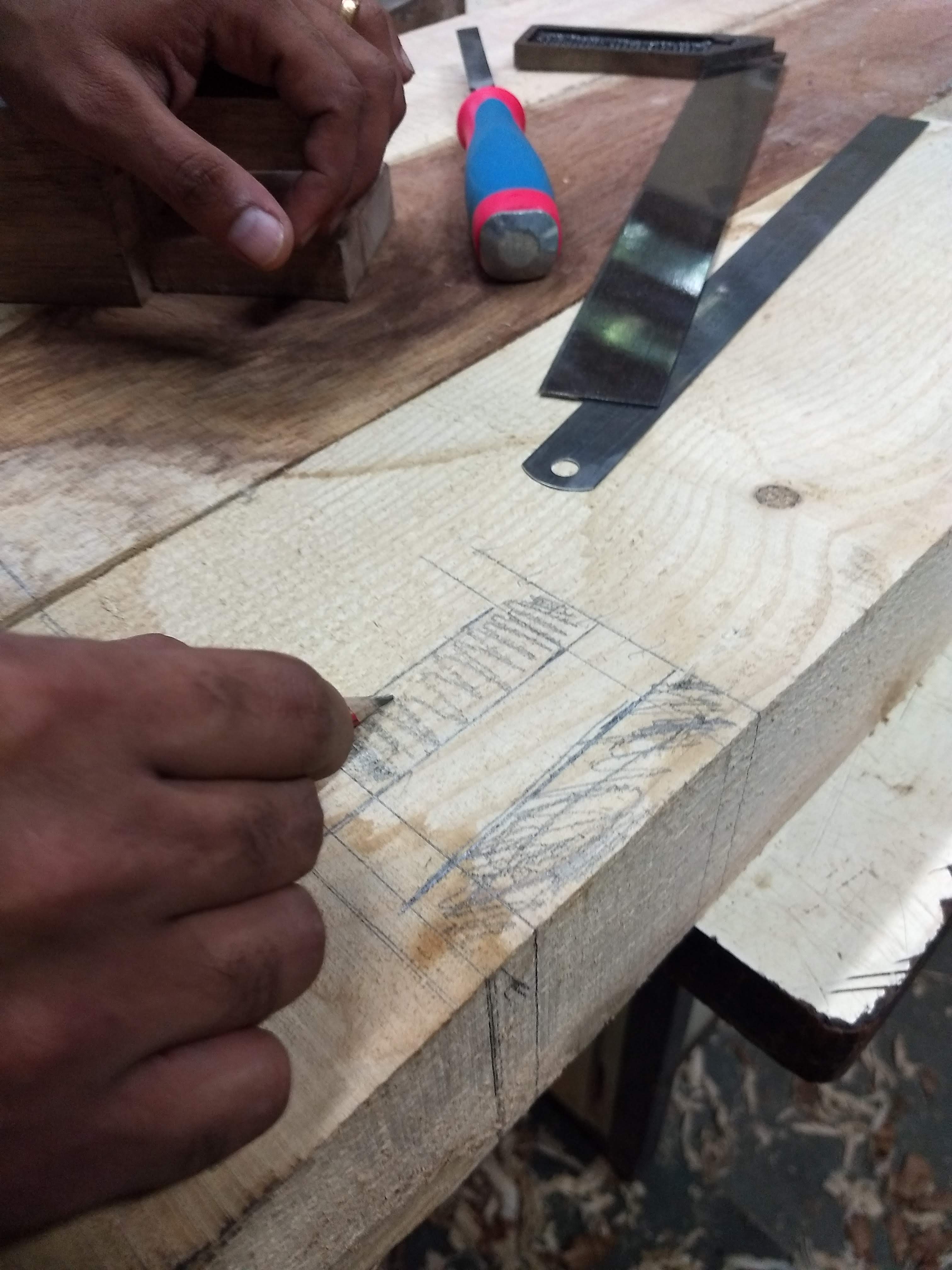
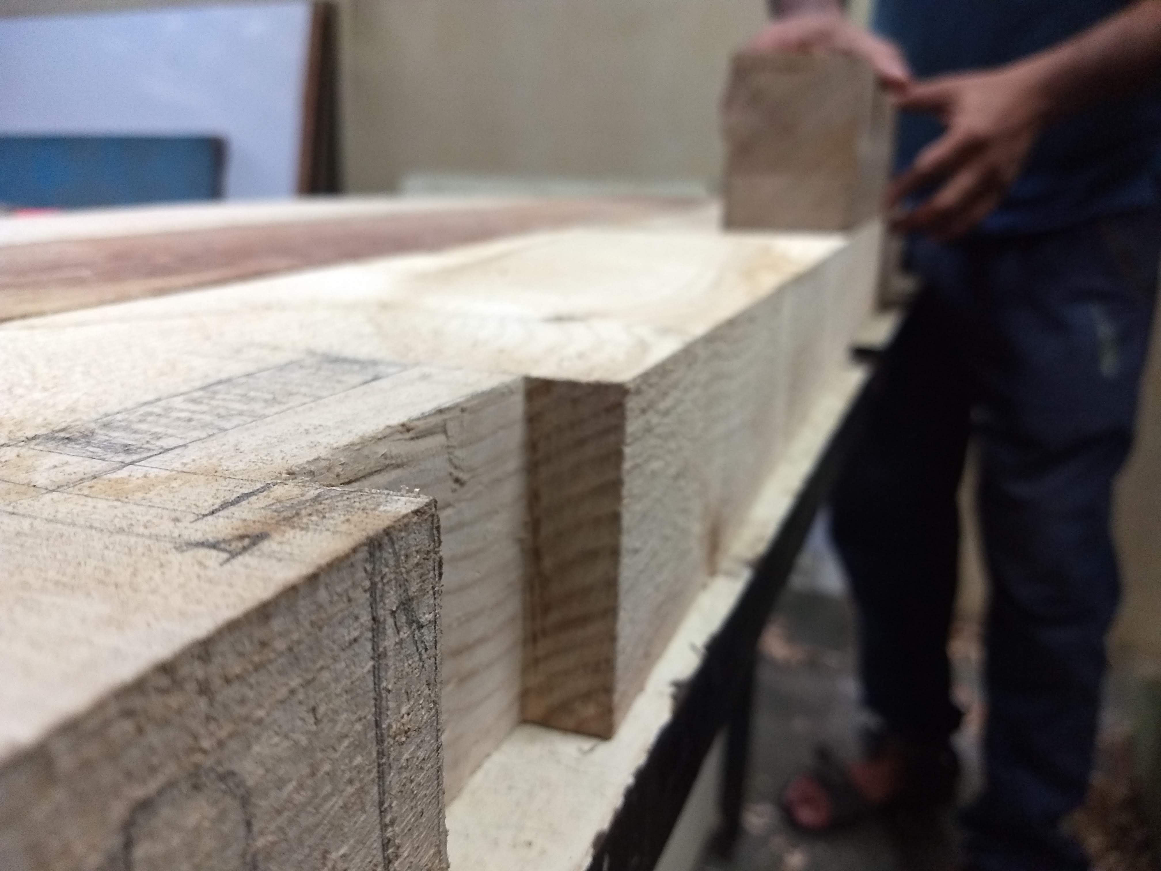
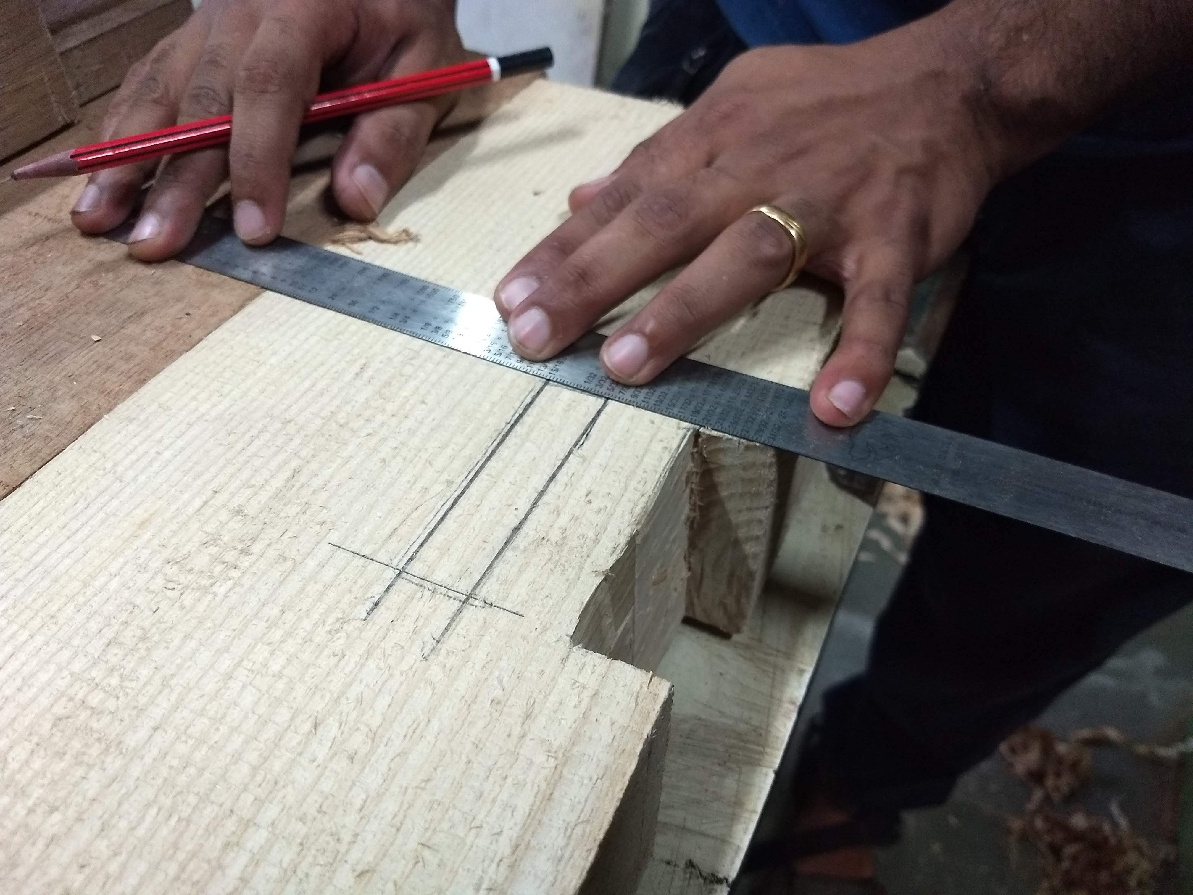
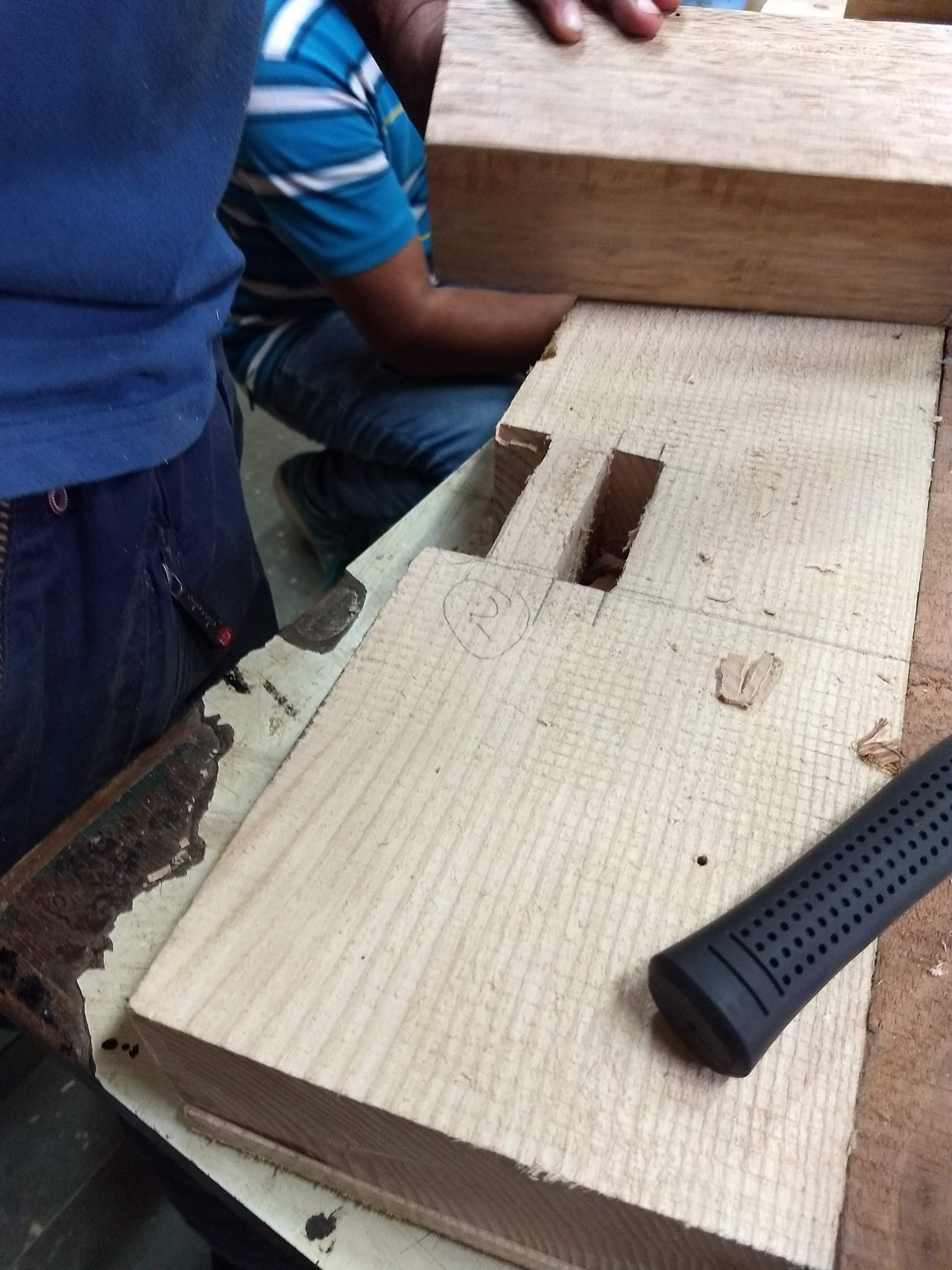
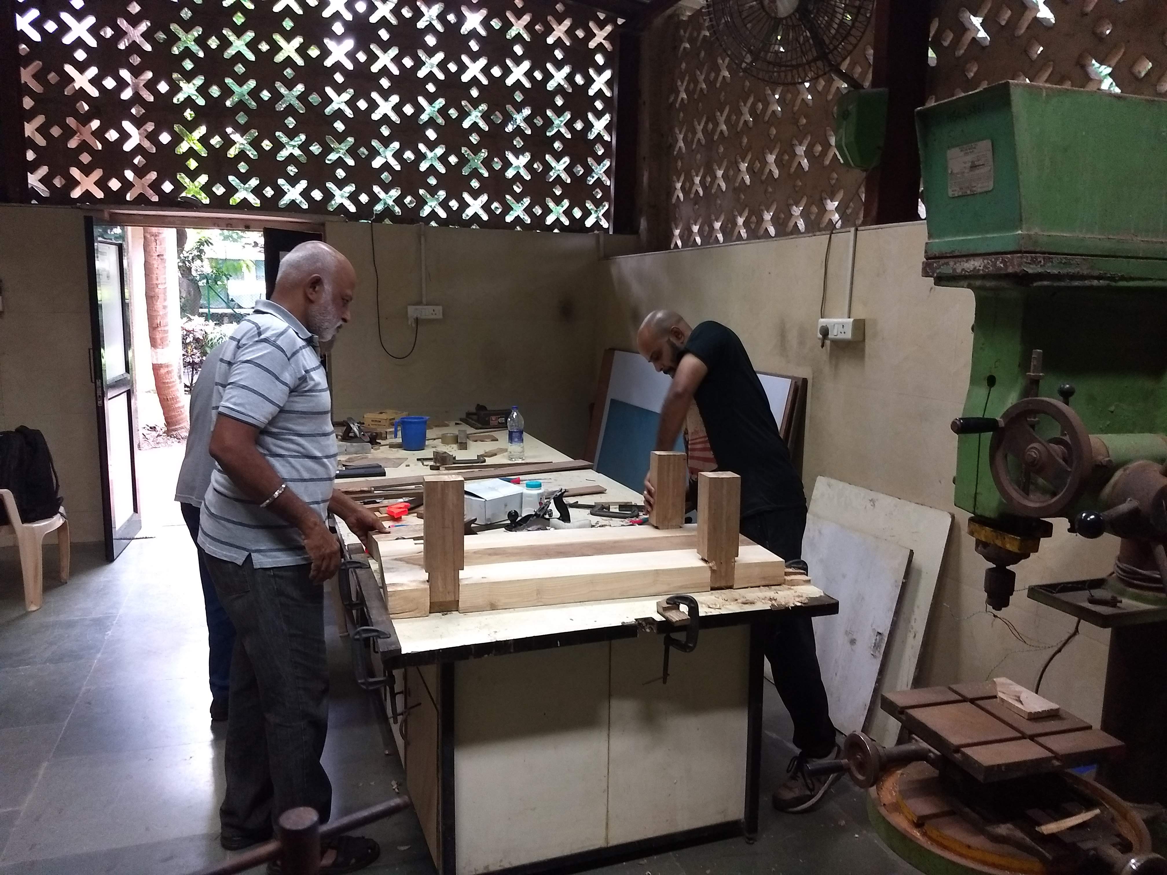
Today’s task requires both patience and accuracy. We need to cut so that the legs can fit on to the base. Since all the 4 legs are not exactly accurate, we have to customize the holes in the base according to the respective legs.
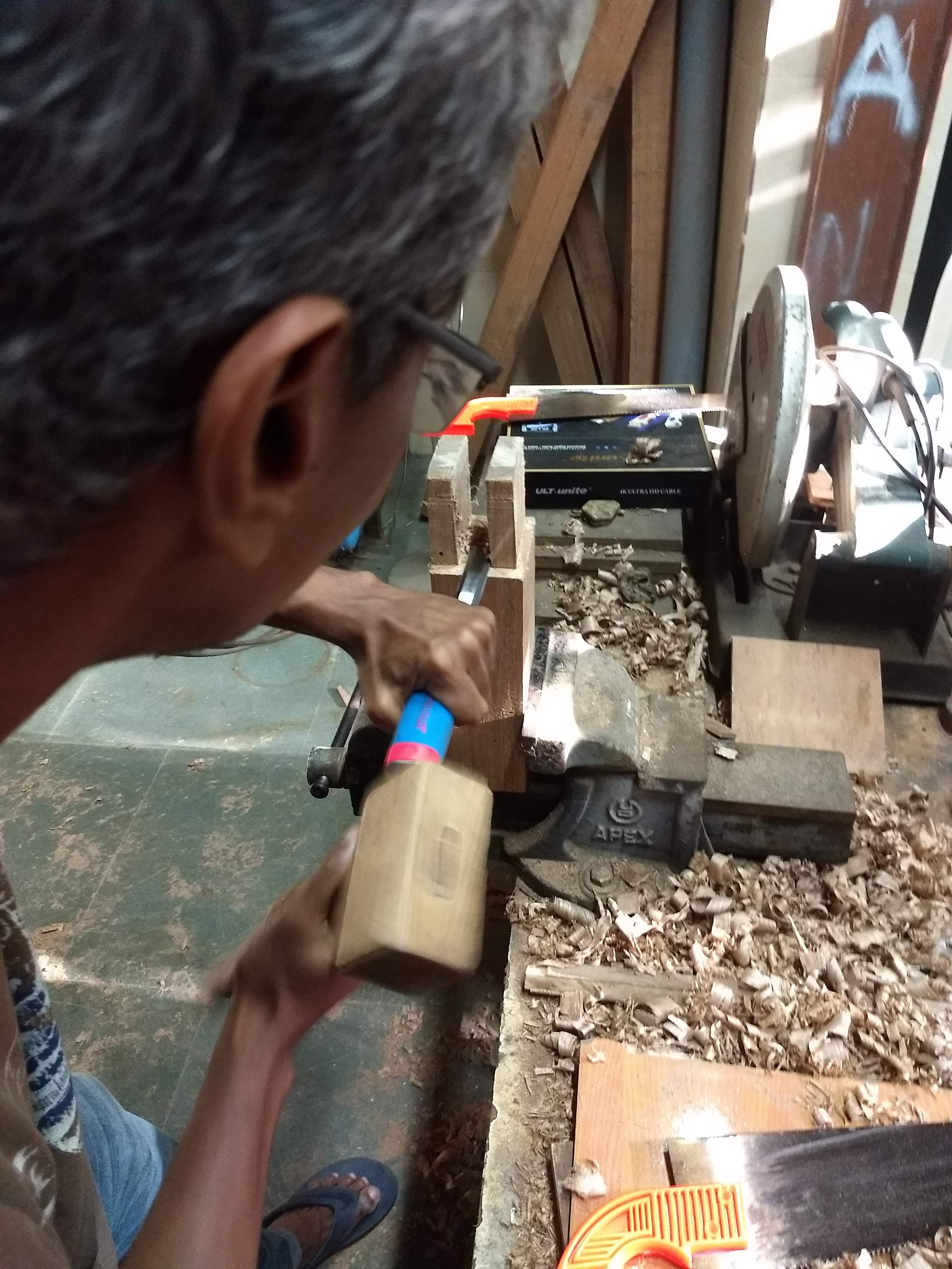
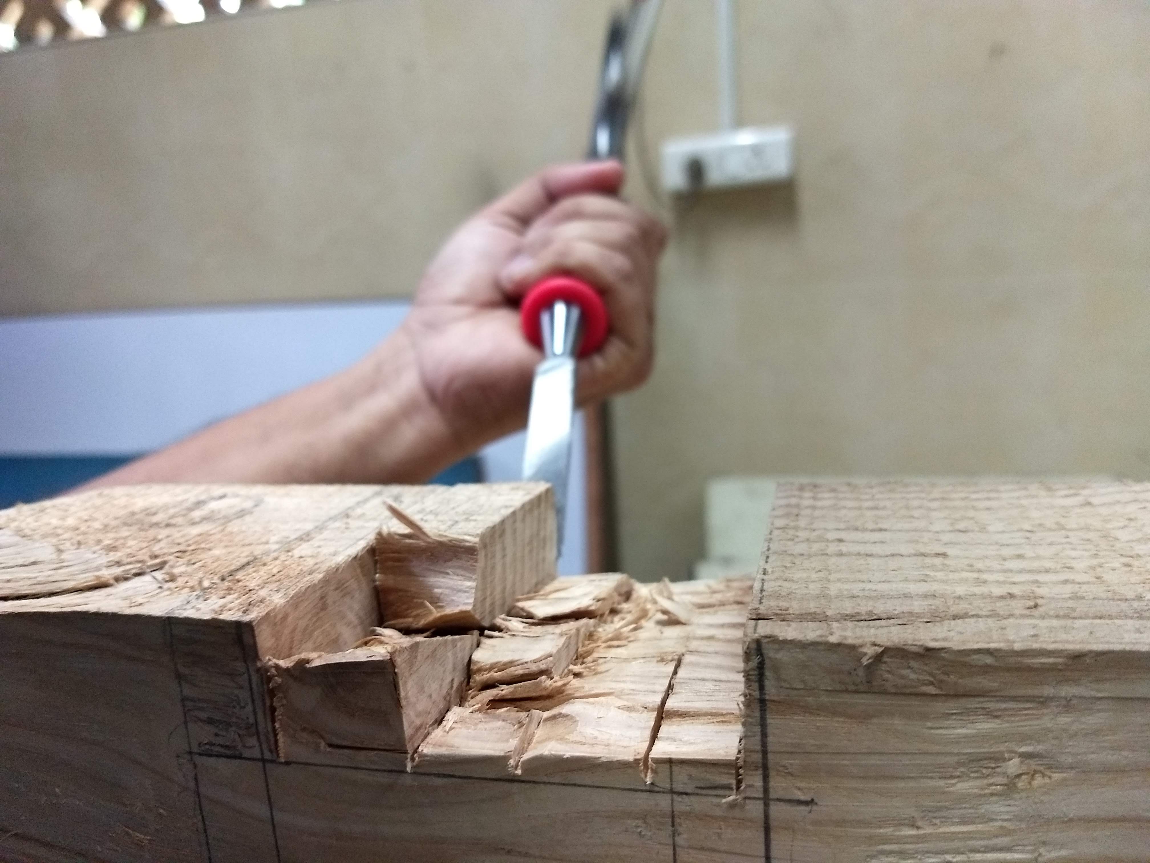
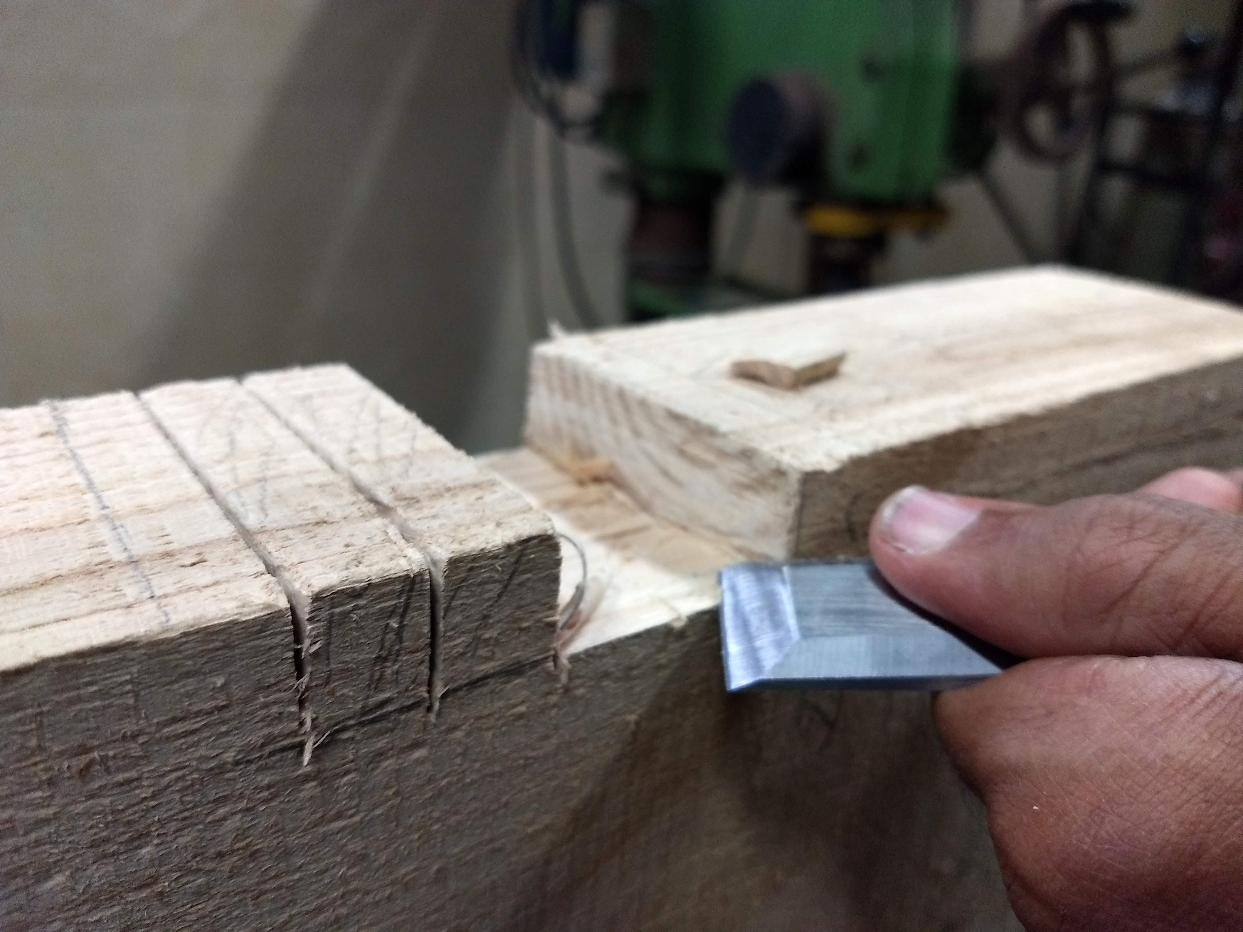
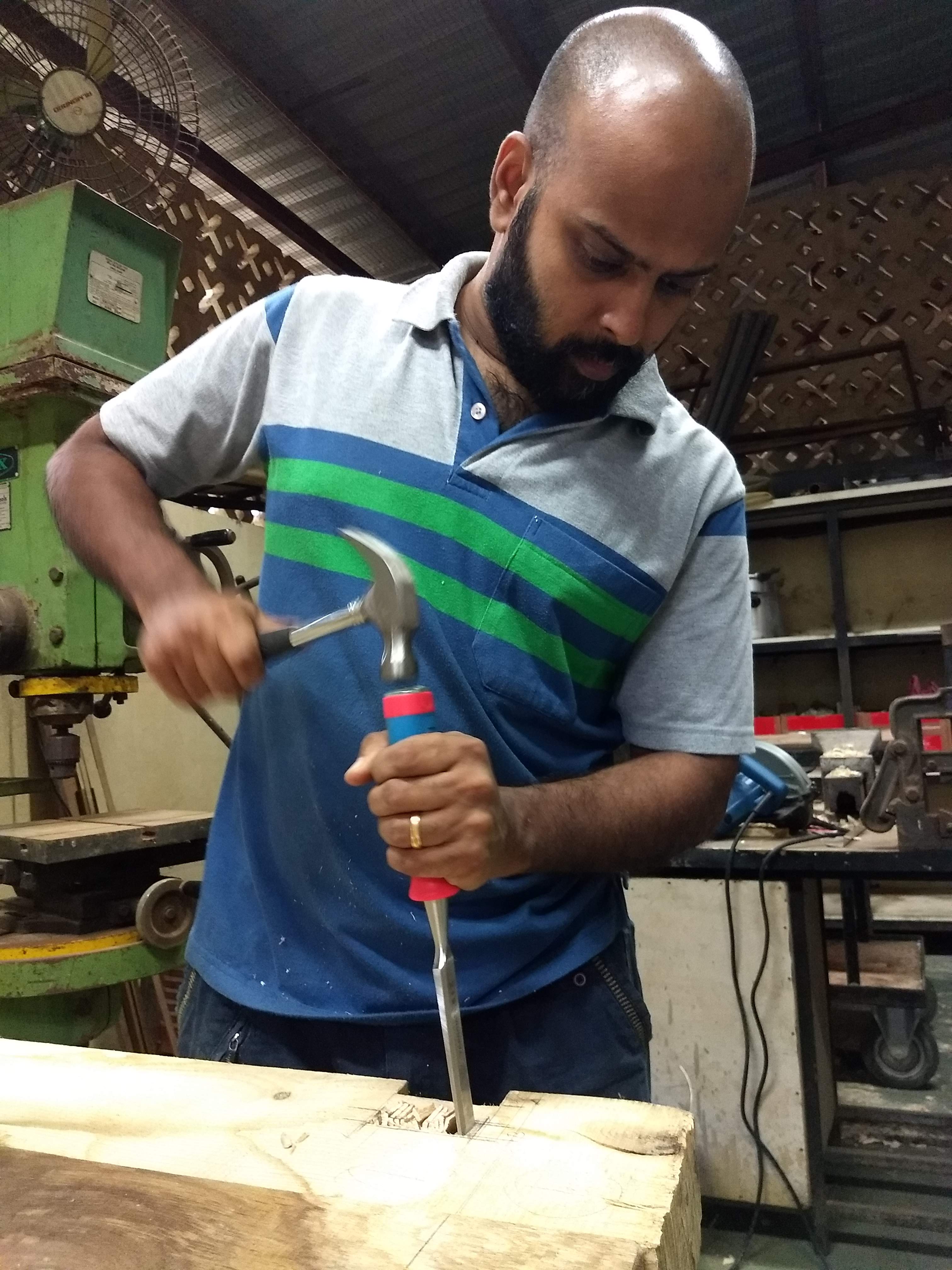
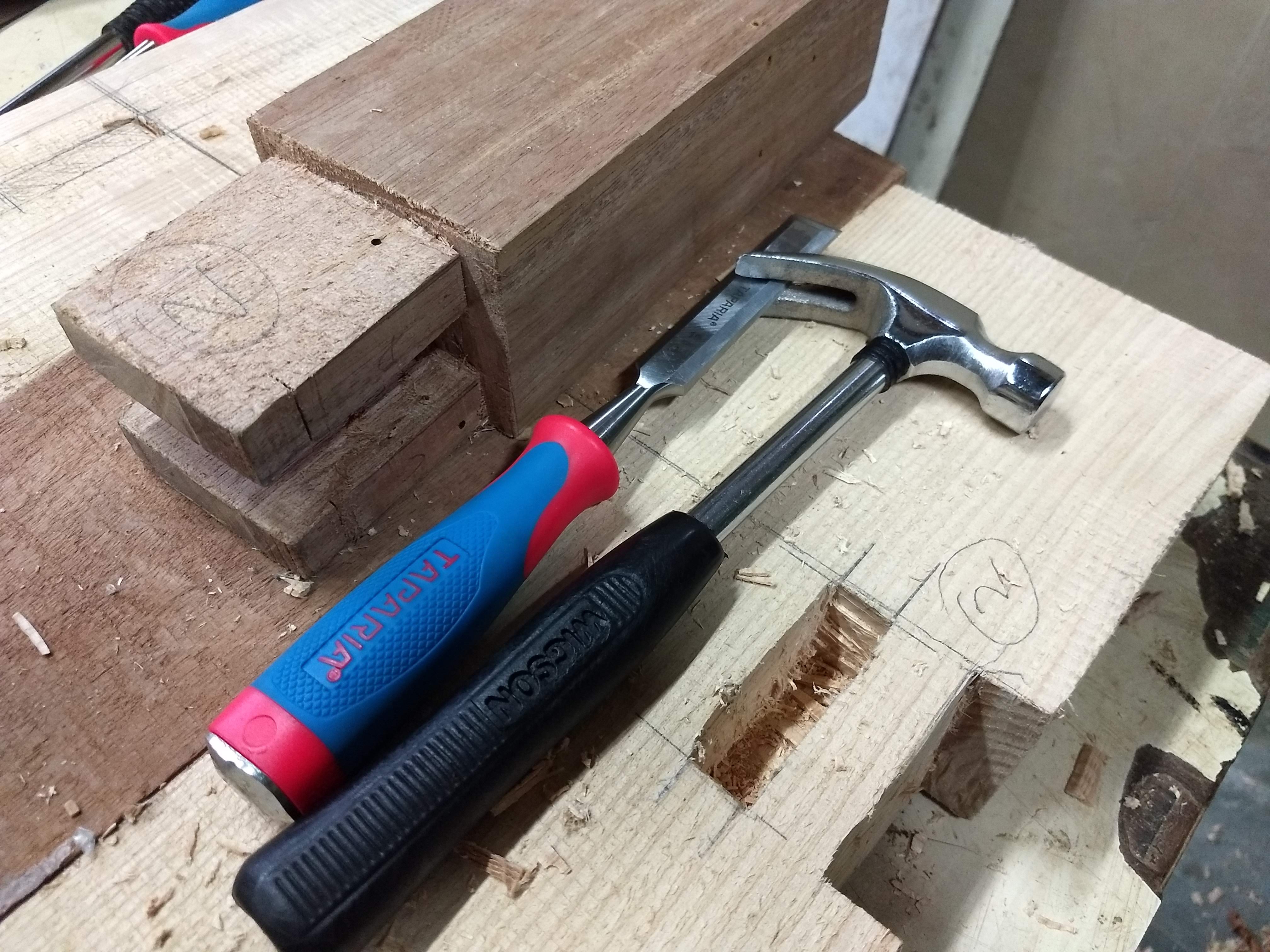
The first two holes were done using hand tools- slowly and steadily. Using a hand saw, chisel and hammer to make series of cut and then to remove the corner end .After that to make a deep cuboid shape cut of around 6 inches deep in the interior. Lastly, the interior walls needed to be smoothed so that the legs can fit in- its should neither be too tight not too loose.
Making the cut with the saw and working to remove the outside piece
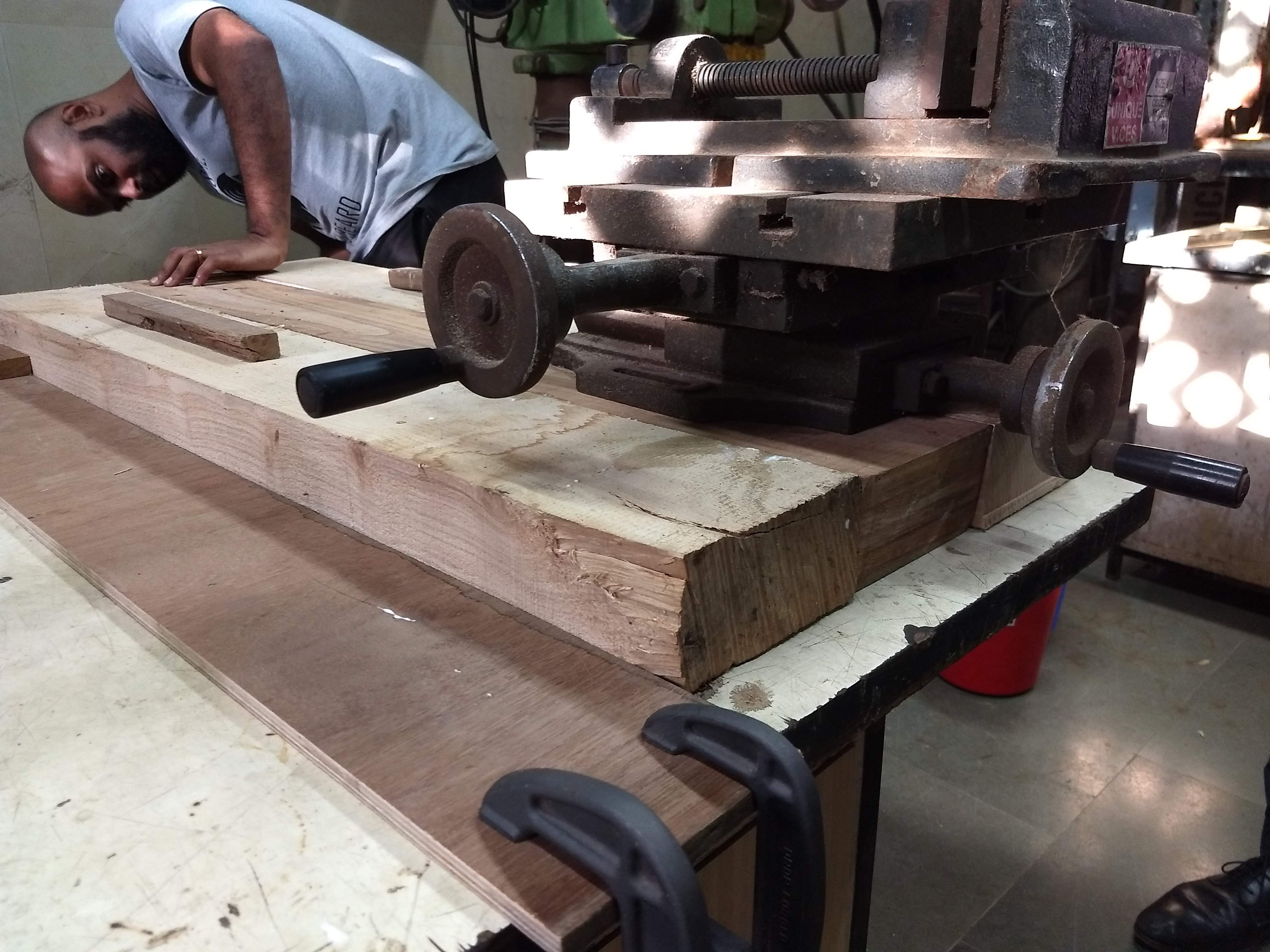
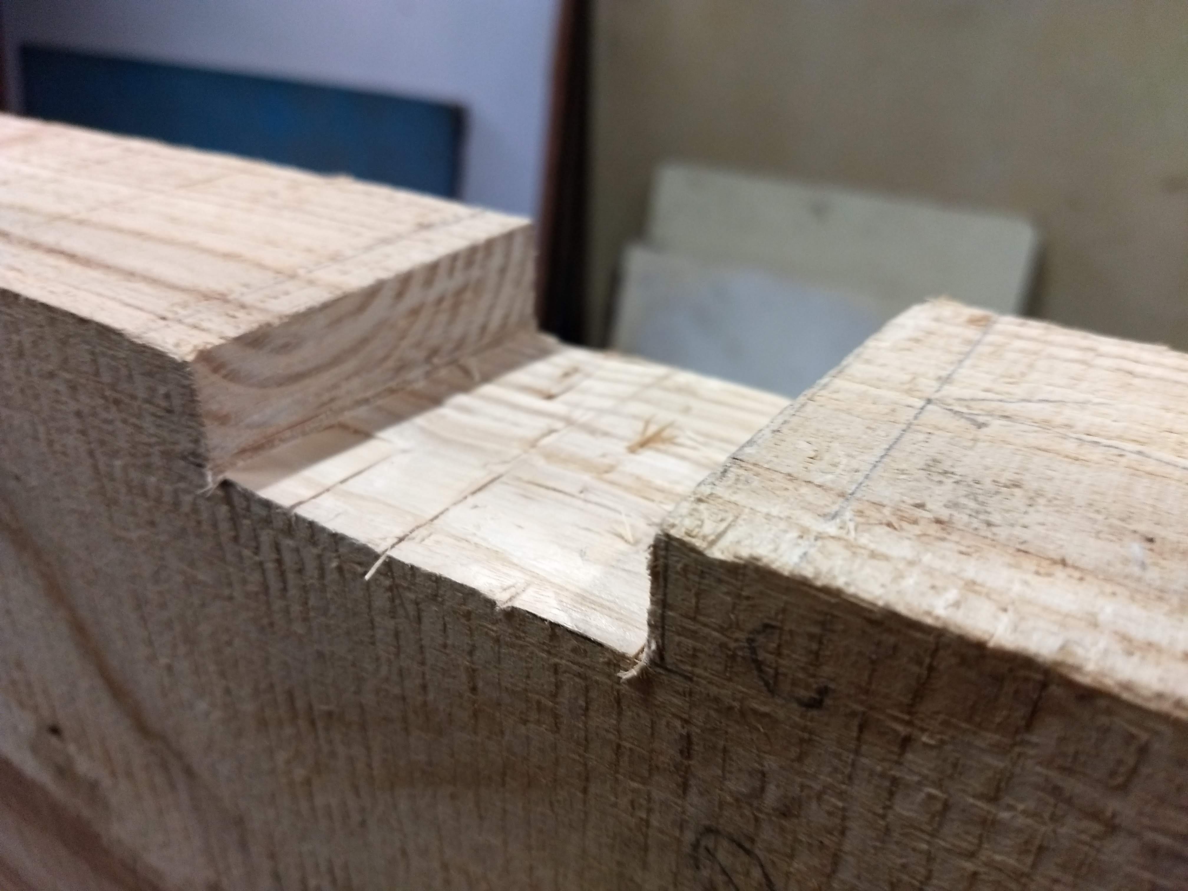
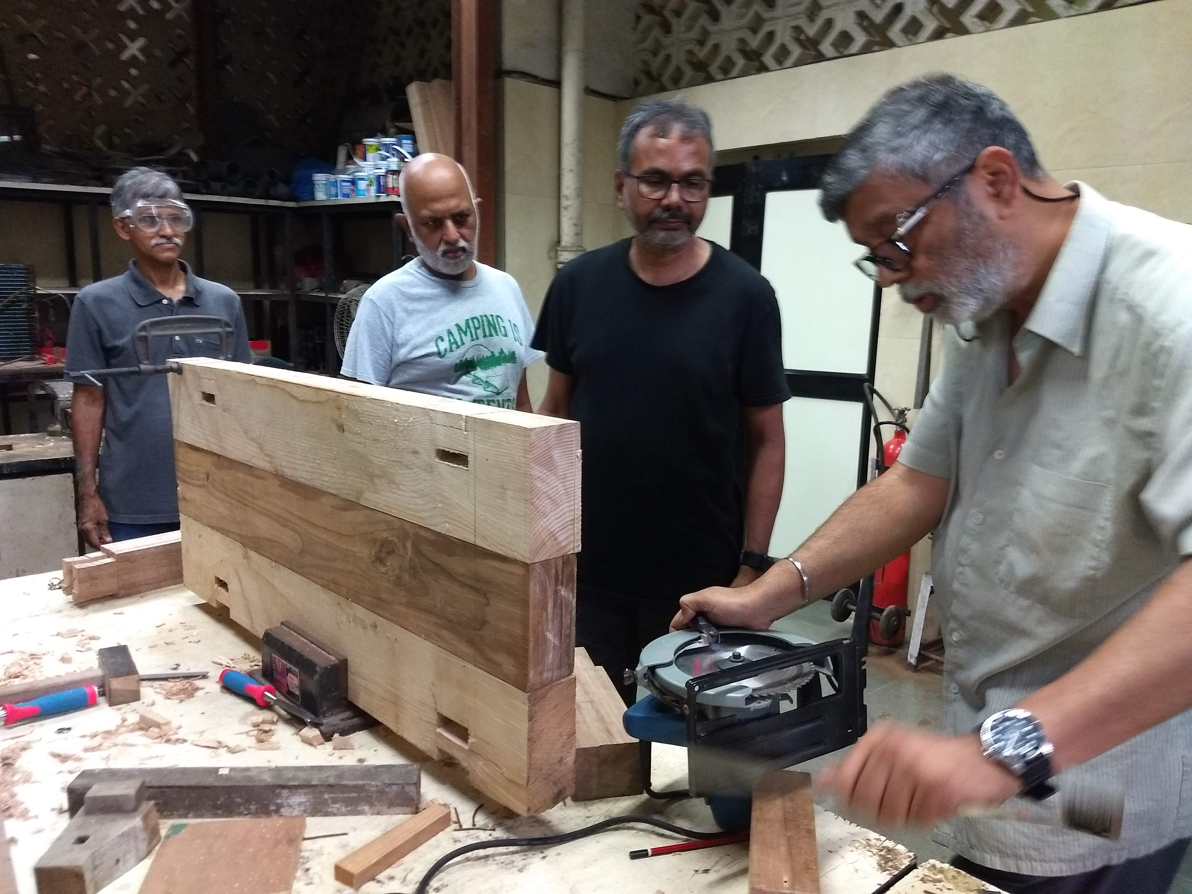
When we were left with the final slot, the team become curious to try another method to achieve the same. We used the industrial drill machine to help us with the process. Here, you can see the team experimenting with both electric circulars saw to make a series of cut initially, and later on using a drill press to make the interior cuboid.
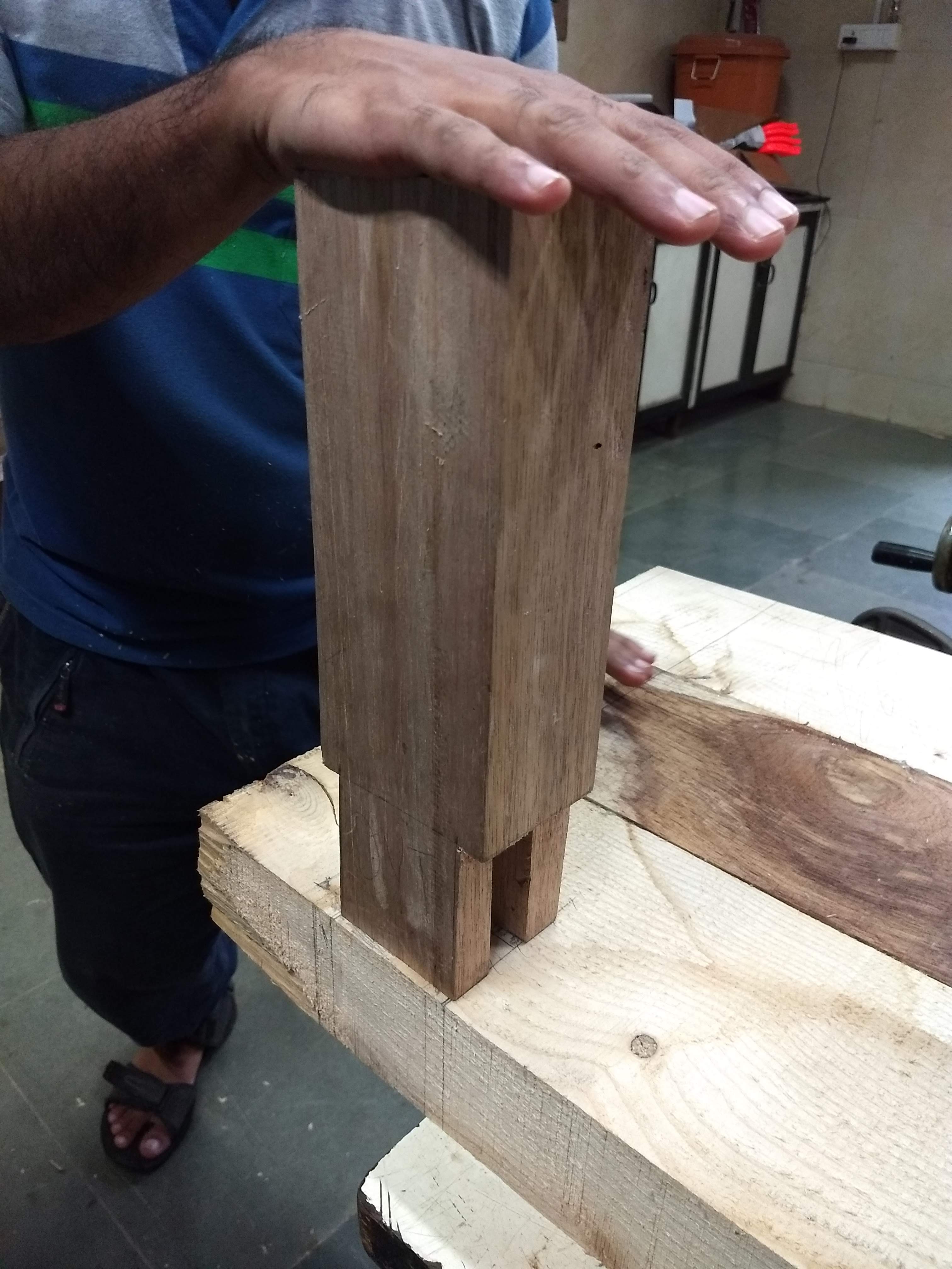
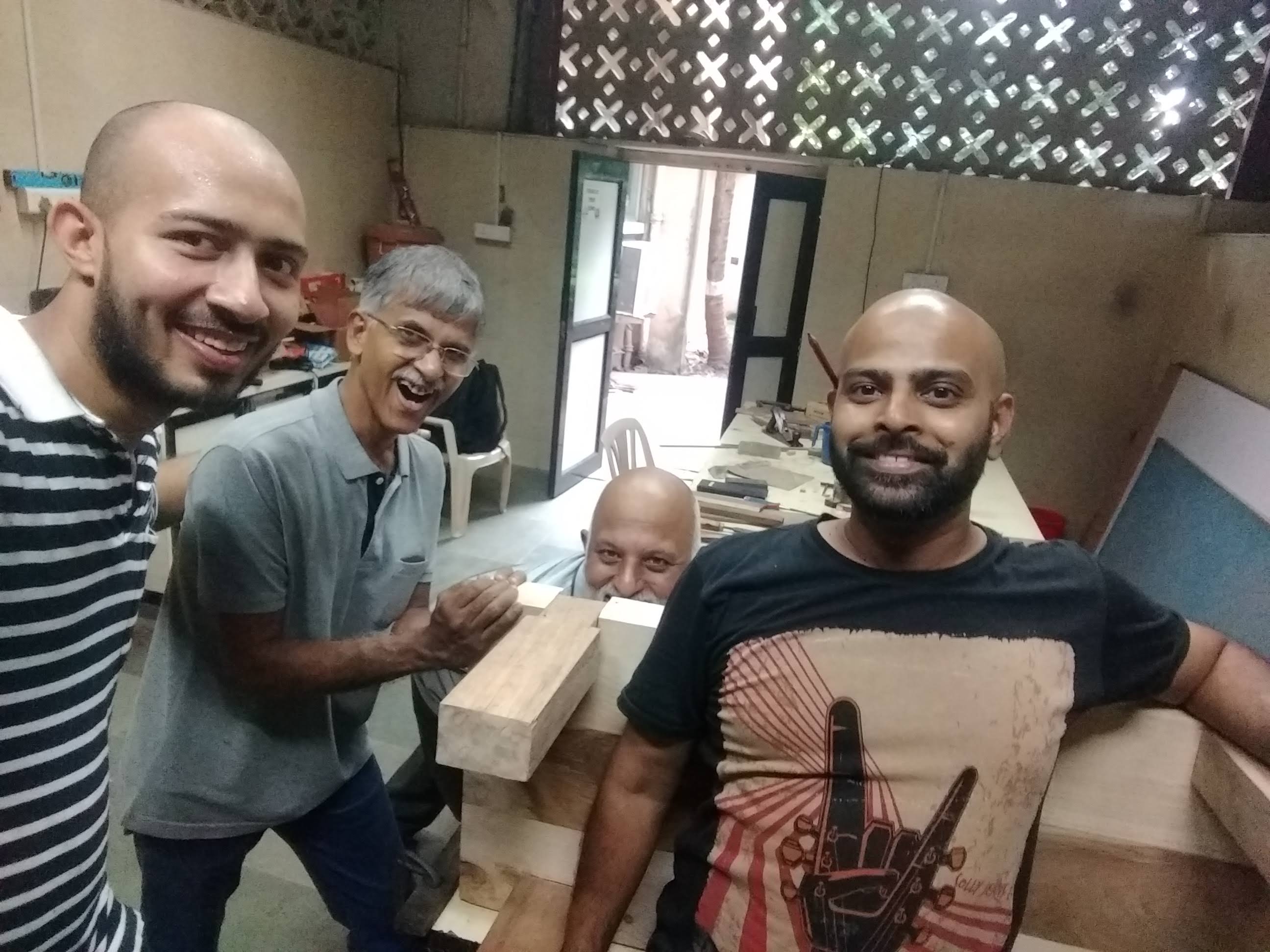
In the second half, the necessary adjustments were made so that the legs fit in the grove properly. This indeed is a meticulous job and requires a lot of patience, estimation, and skill. Finally, when the legs were plugged in, the extra part on top was removed and smoothed.
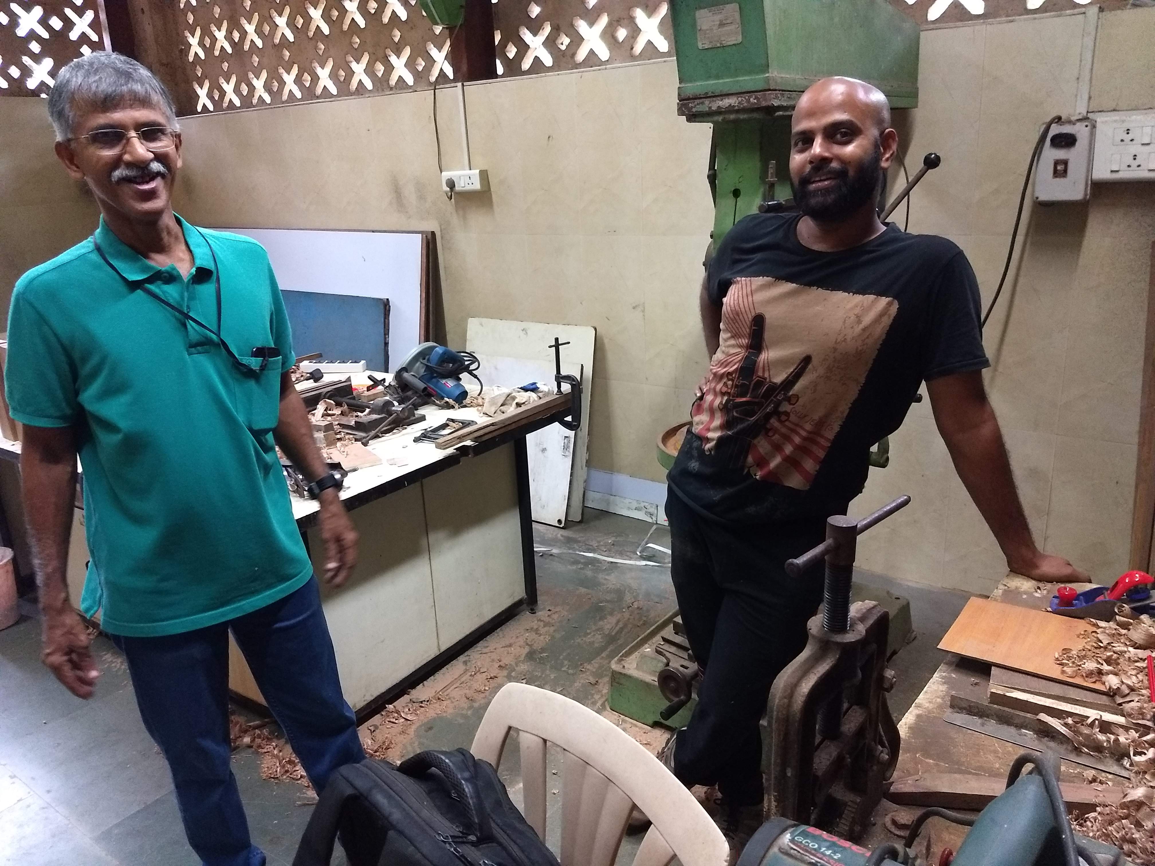
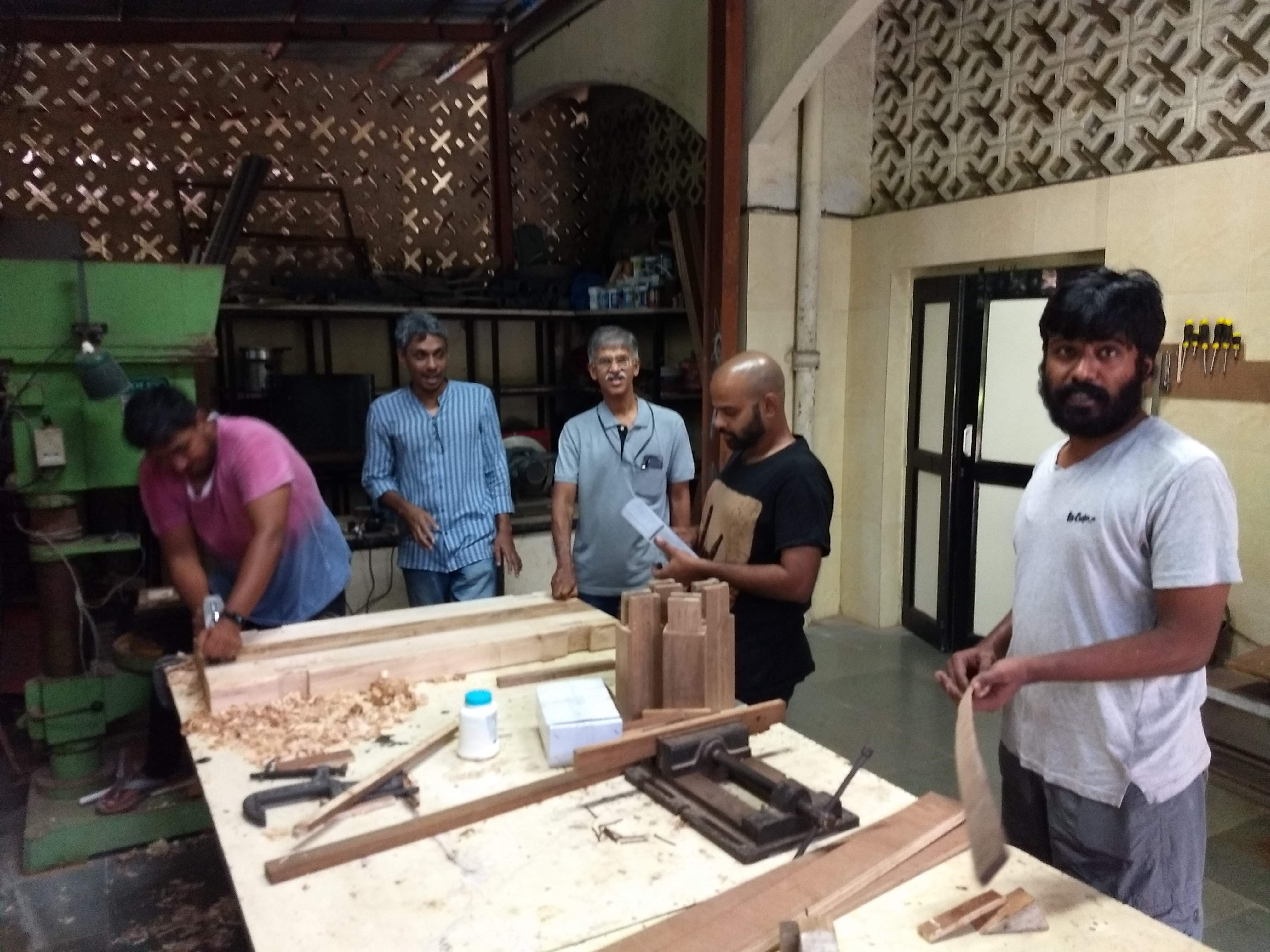
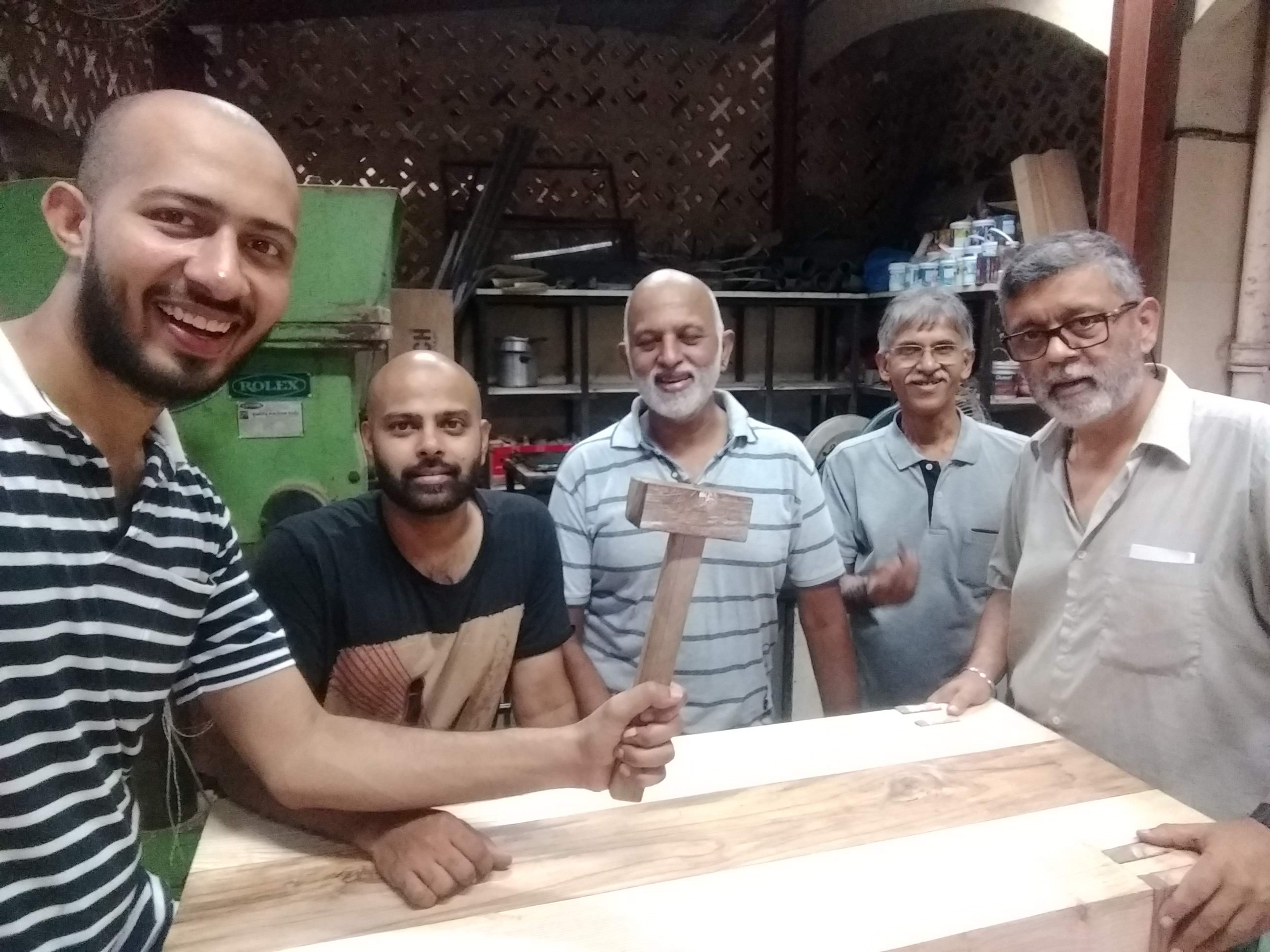
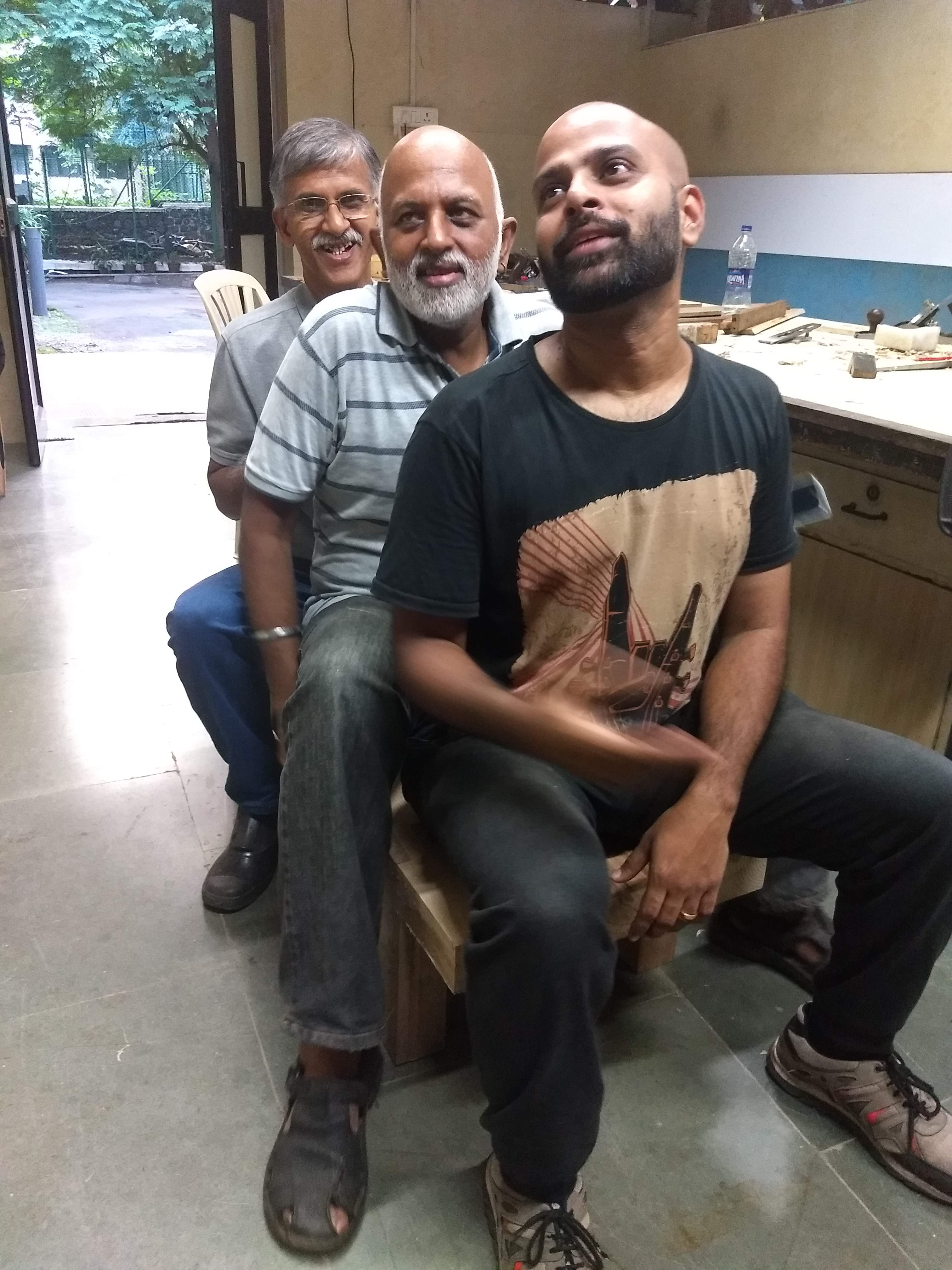
We would sincerely like to express the deepest gratitude to all the members who were involved in the project. Viren for being a superb mentor, Puneet for seeding the idea , Jude, GN, KS, VK, Ashish, Manoj, Shashank, Deborah, DP, Anil Sir, Cosmetic Staff, technical team, and all the other communities members for contributing in various capacities towards the completion of the project.
What’s next?
Use wood putty to fill in the cracks in the workbench - around the legs
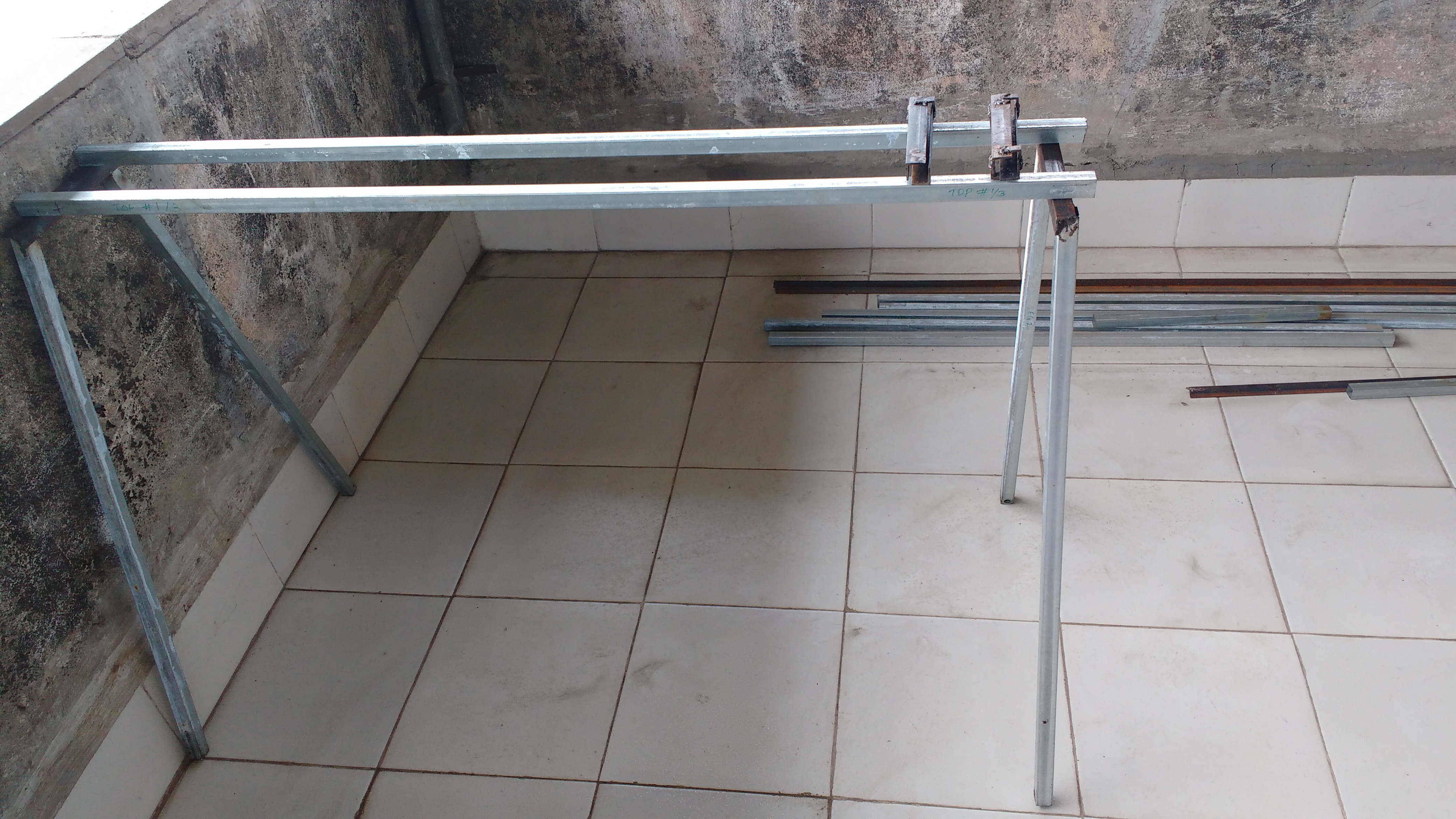
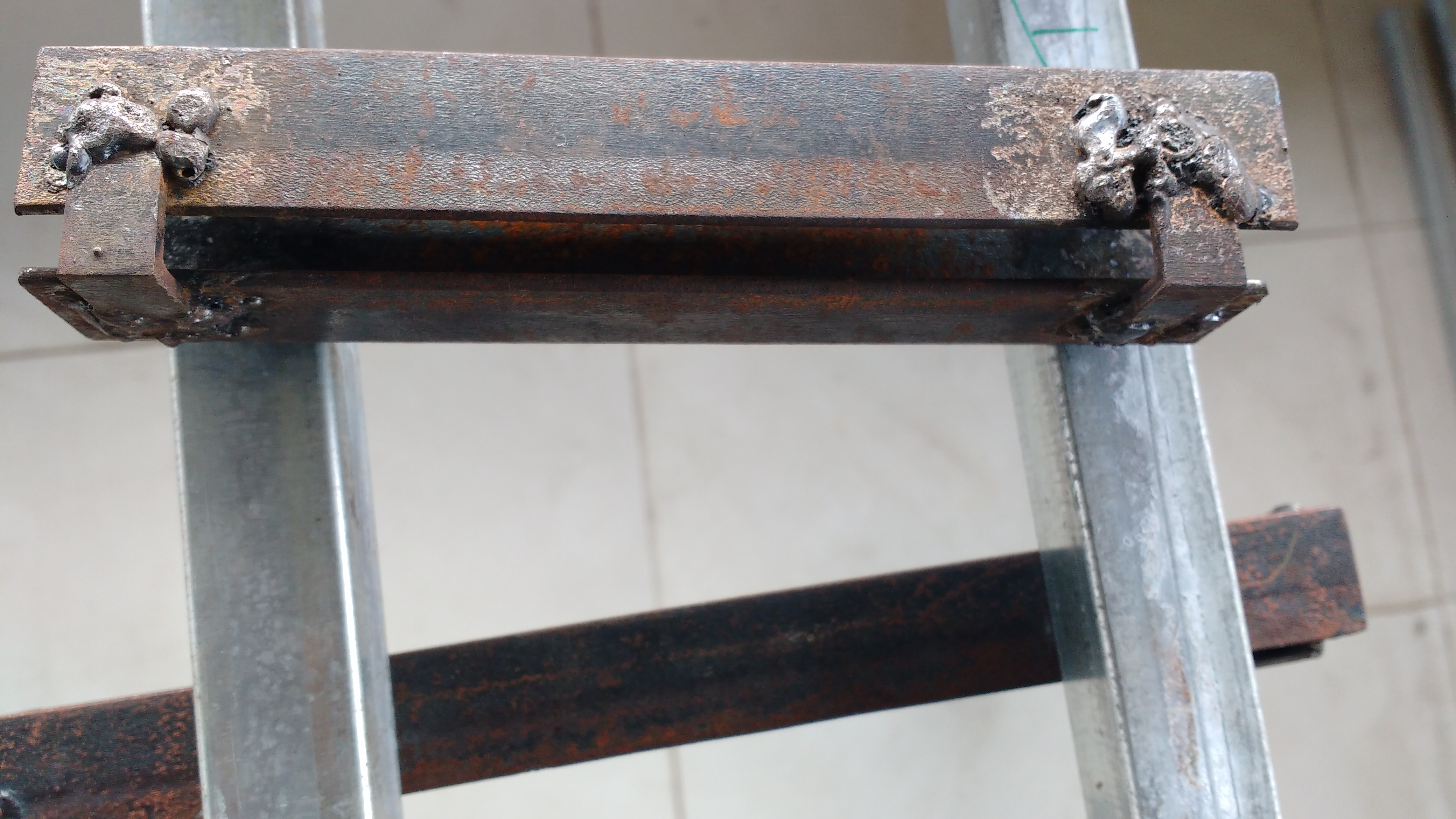
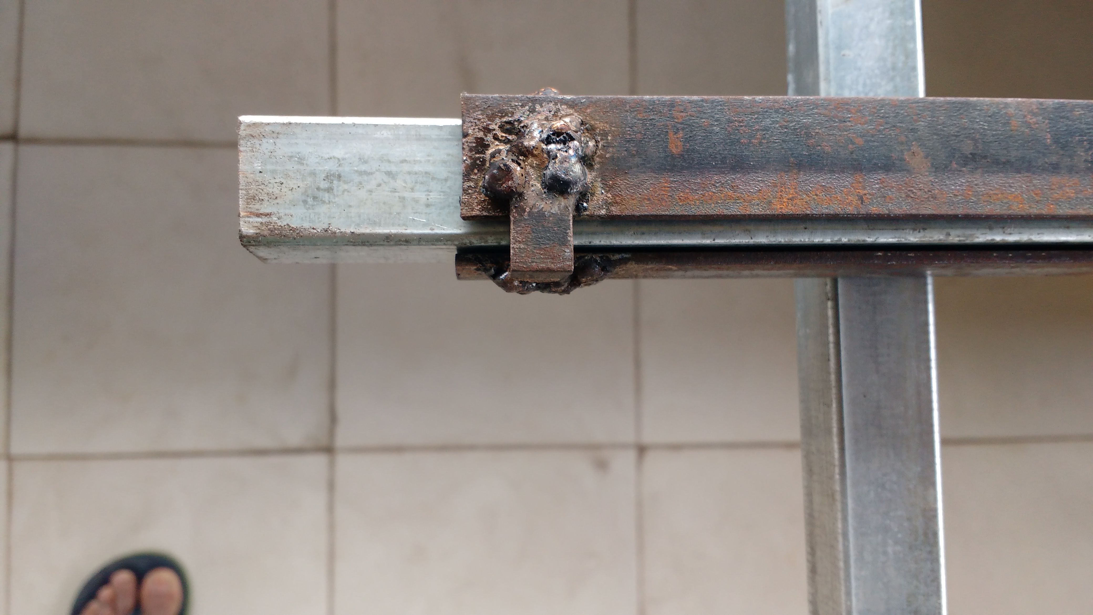
I felt the need for a saw horse cum welding table. @Pneb wanted the working height different from what I need, the height has to be adjustable. Since the height has to be adjustable, might as well make it sufficiently adjustable to work standing or seated. Talk of feature creep!
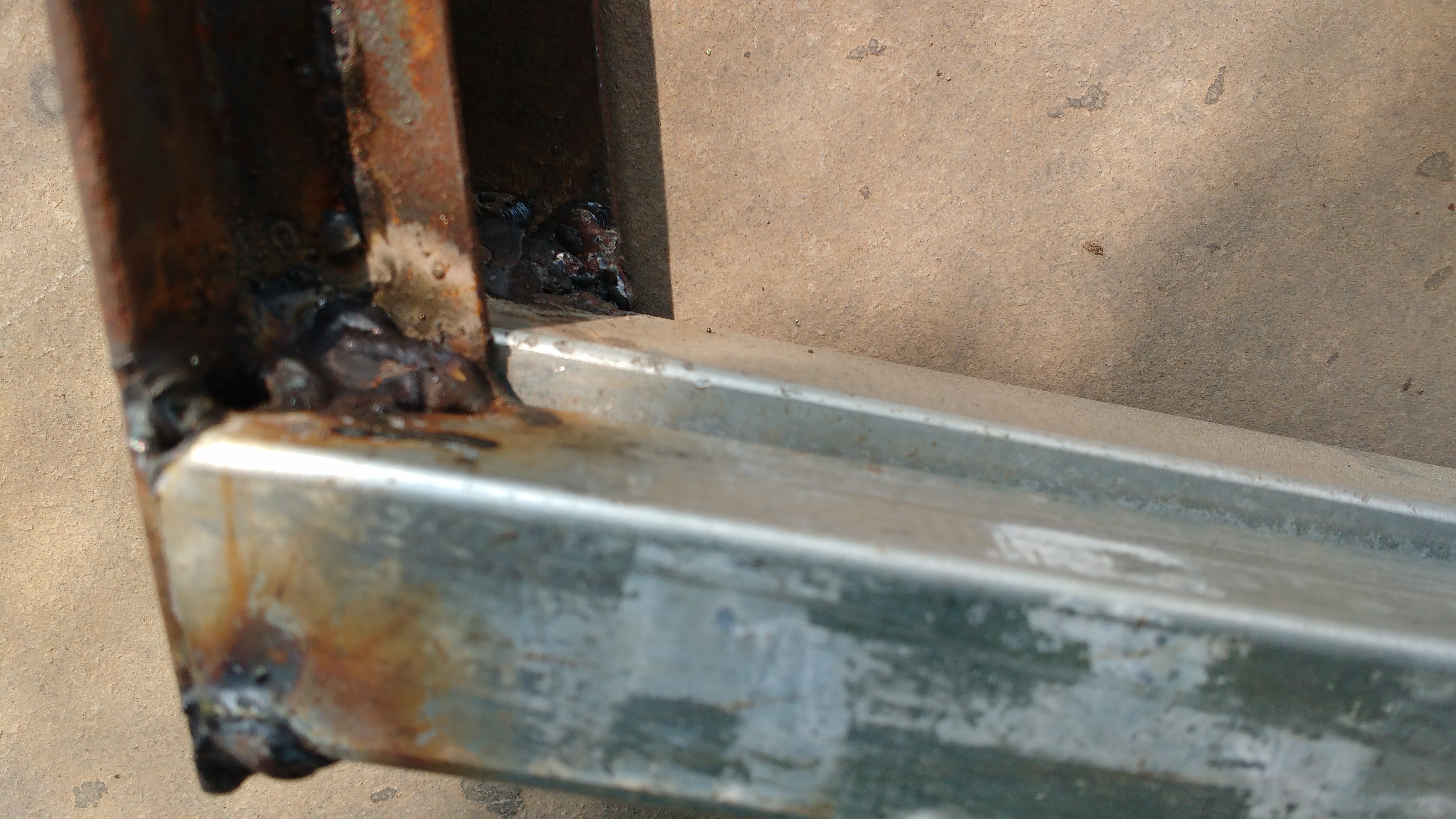
Some images from the ongoing endeavor:
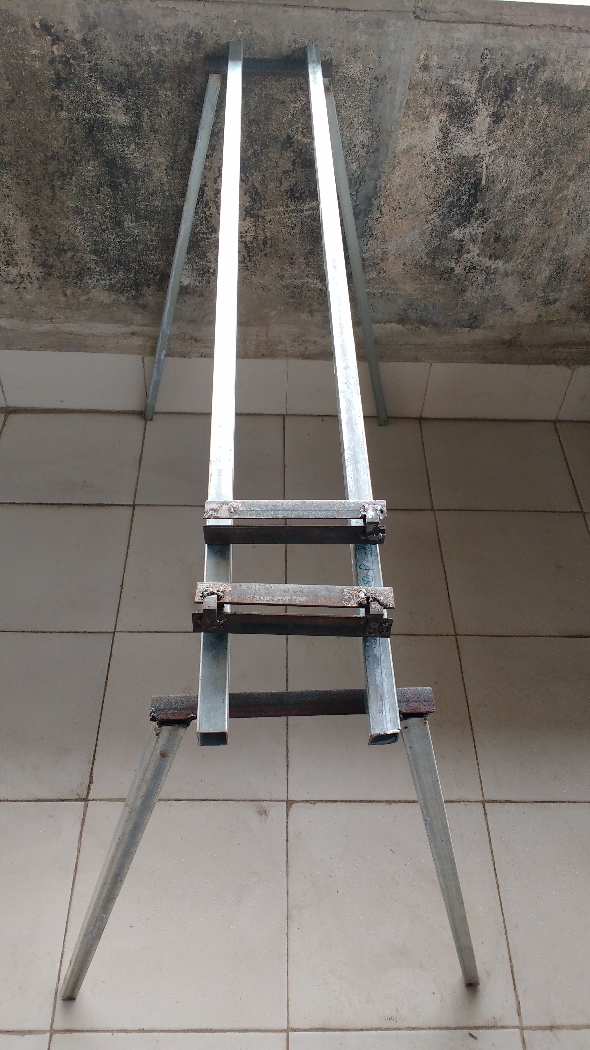
Legs with an angled cut of $11^o$ welded to the top.
Four of these will be used, 2 on each leg frame. Top frame will be fixed to the sliding section.
Four sockets are used to provide maximum stability. However that makes adjustment difficult if you are alone. Ideally a crank mechanism…feature creep again!
Notice the play at the end of the video? this will make the top shake approx 2 mm. The gap between slide and socket was created by wrapping some news paper around the slide - 3 layers. Which makes six layers on two opposite faces. Gap might be reduced by using only 2 layers in the rest of the sockets.
I think it might have been more practical to create a second height adjusting platform, with dogs to secure the saw frame.
By combining them or fiddling with a stable ‘horse’ (just couldn’t resist it ), a structure of good stability is being compromised.
A practical, although maybe more expensive in theory, very stable height adjusting platform for heavy duty work could be jerry rigged from an automobile hydraulic hand lift.


