Day 4
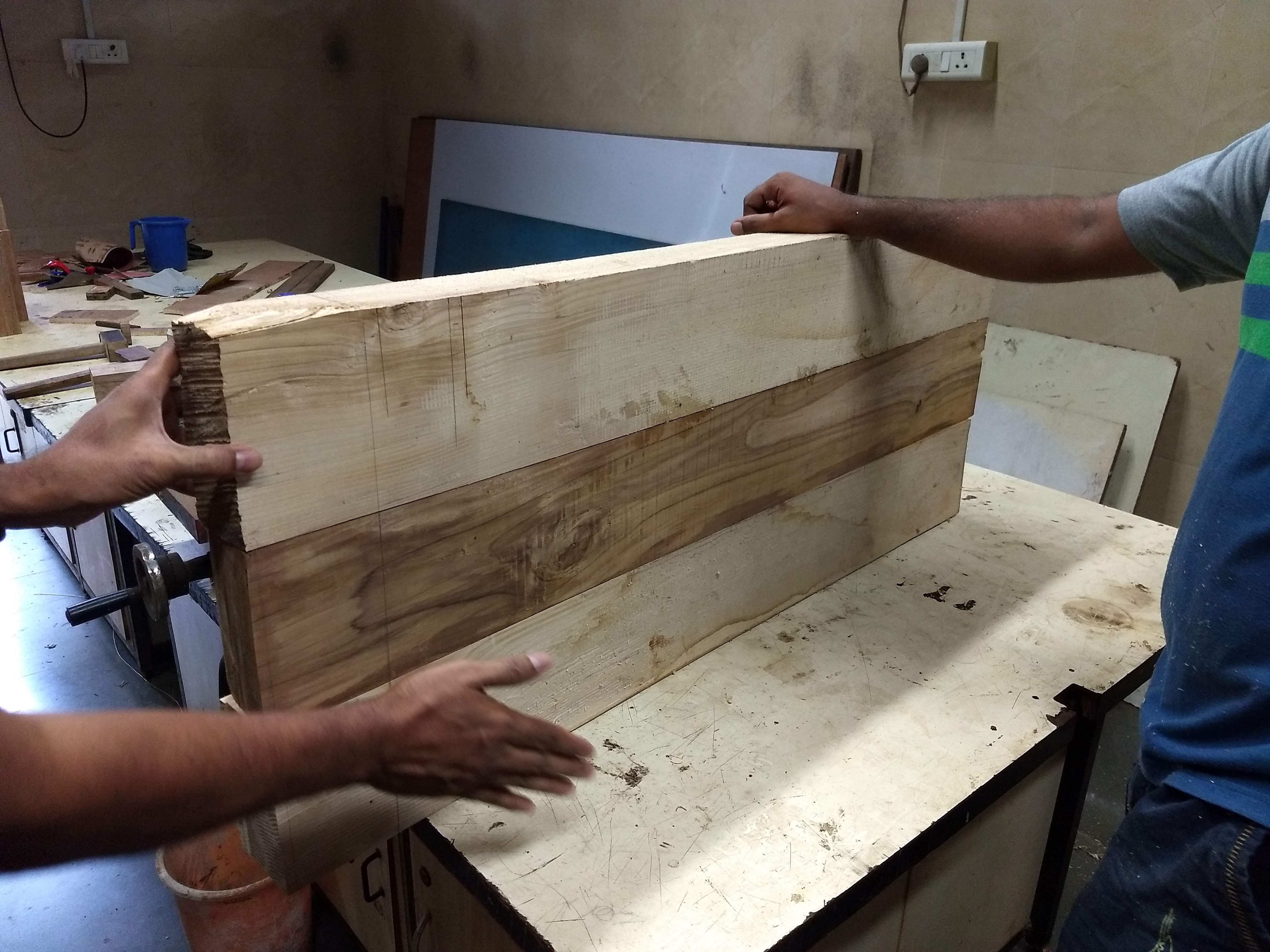
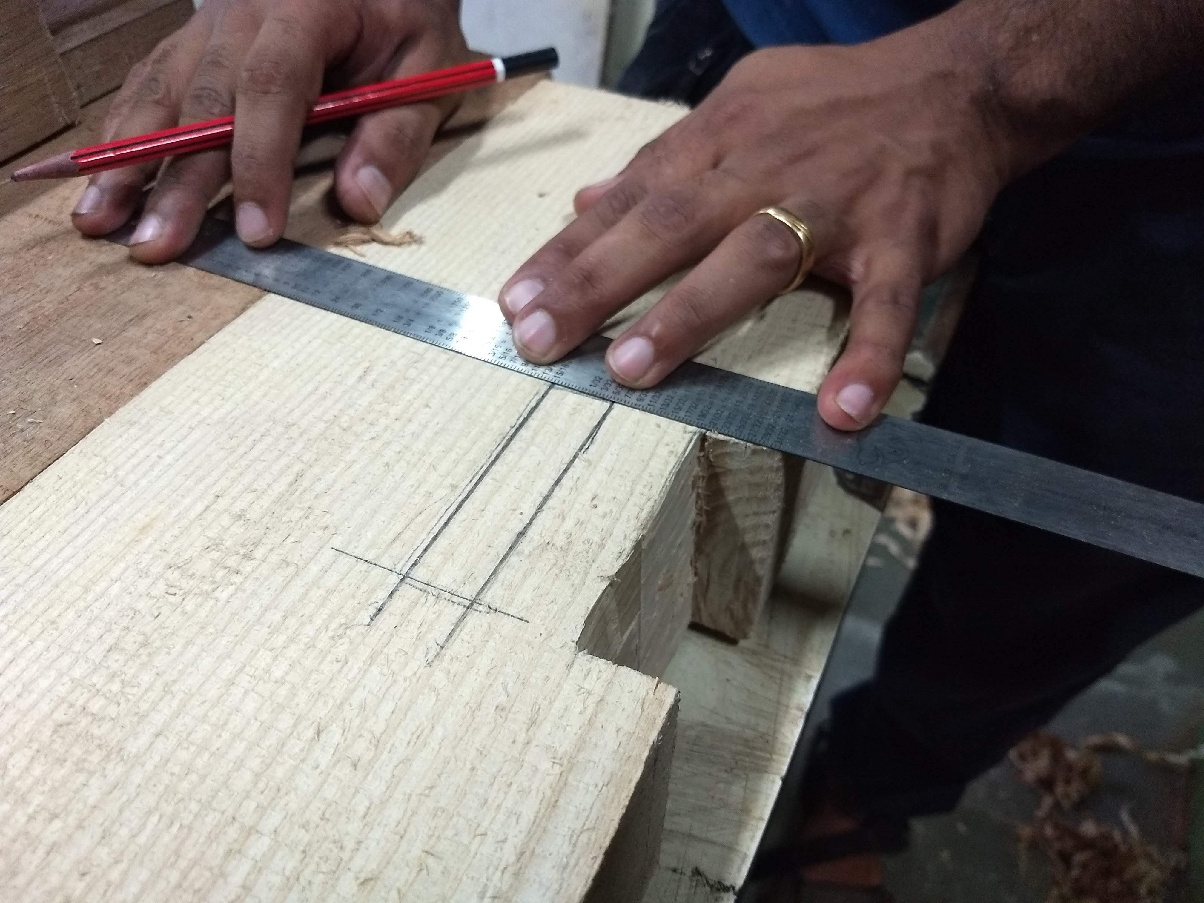
Today’s task requires both patience and accuracy. We need to cut so that the legs can fit on to the base. Since all the 4 legs are not exactly accurate, we have to customize the holes in the base according to the respective legs.
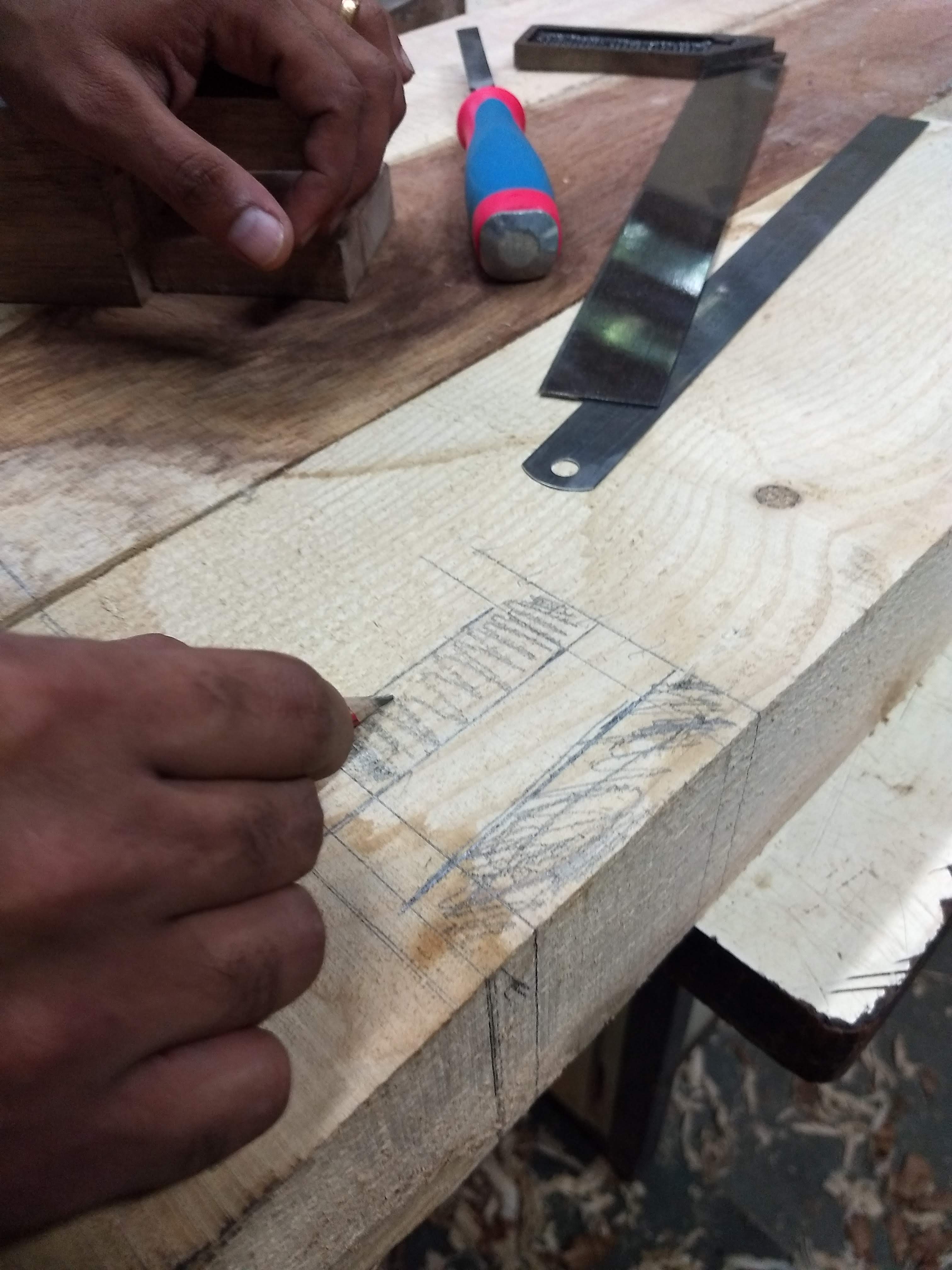
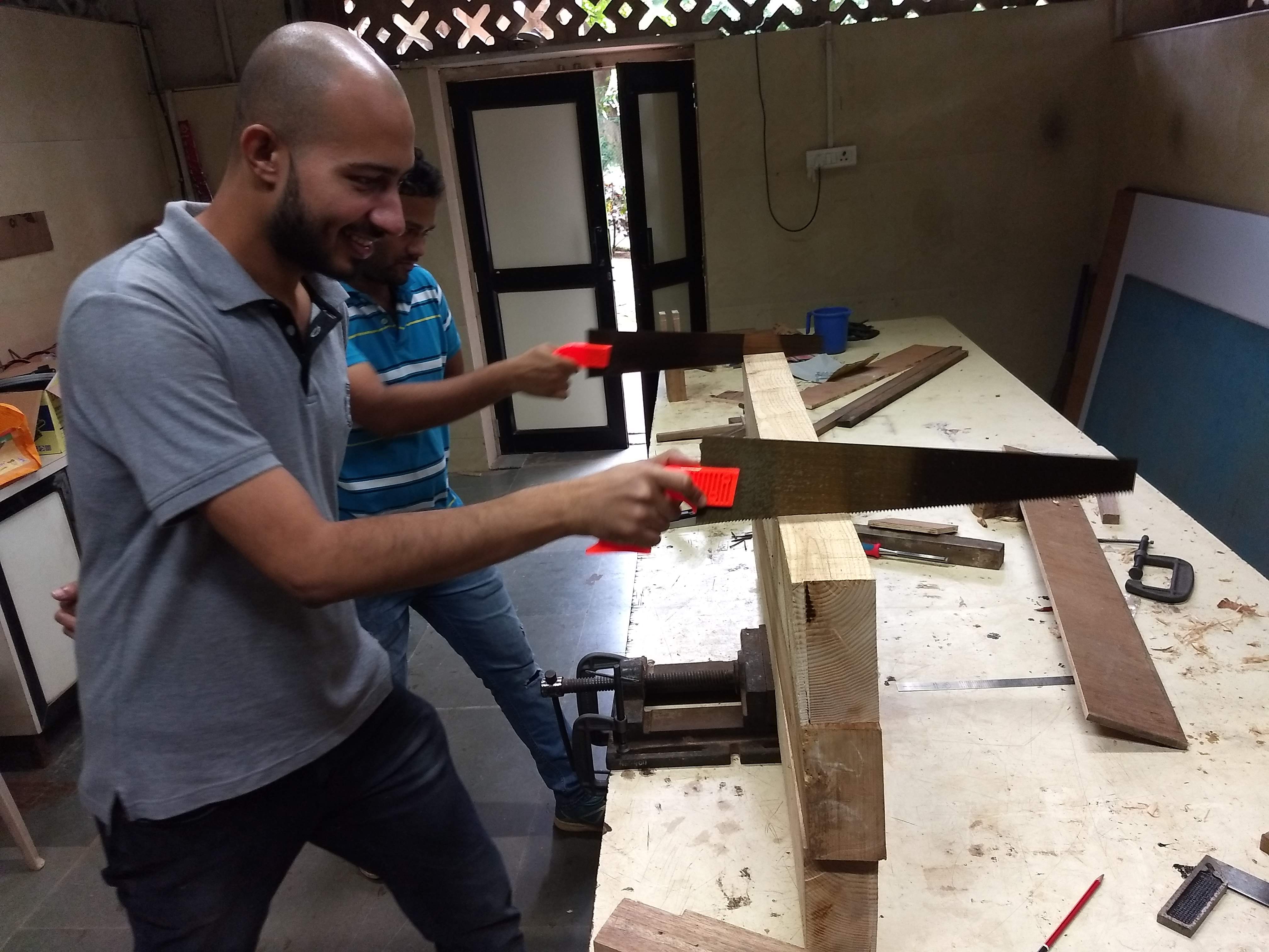
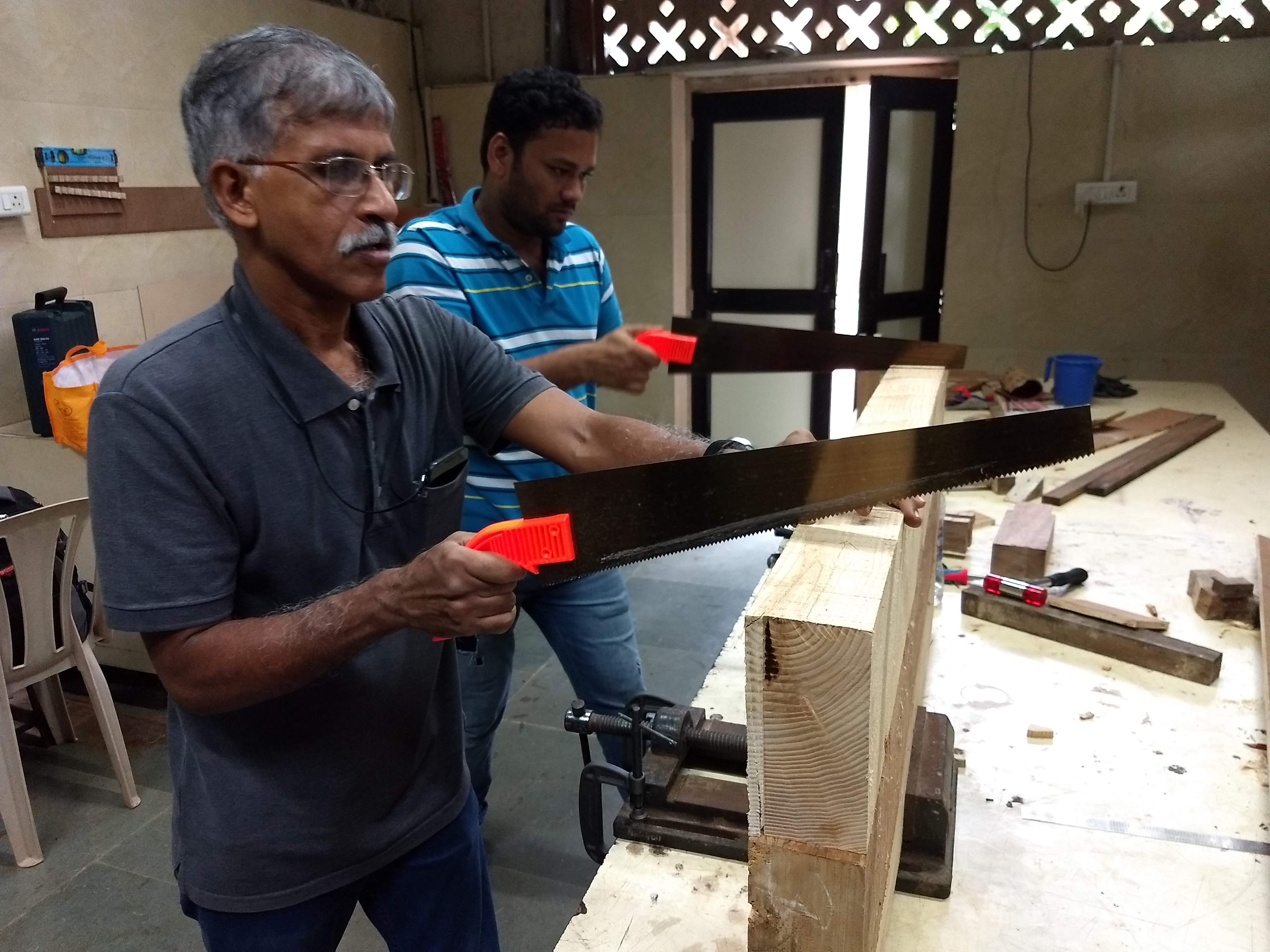
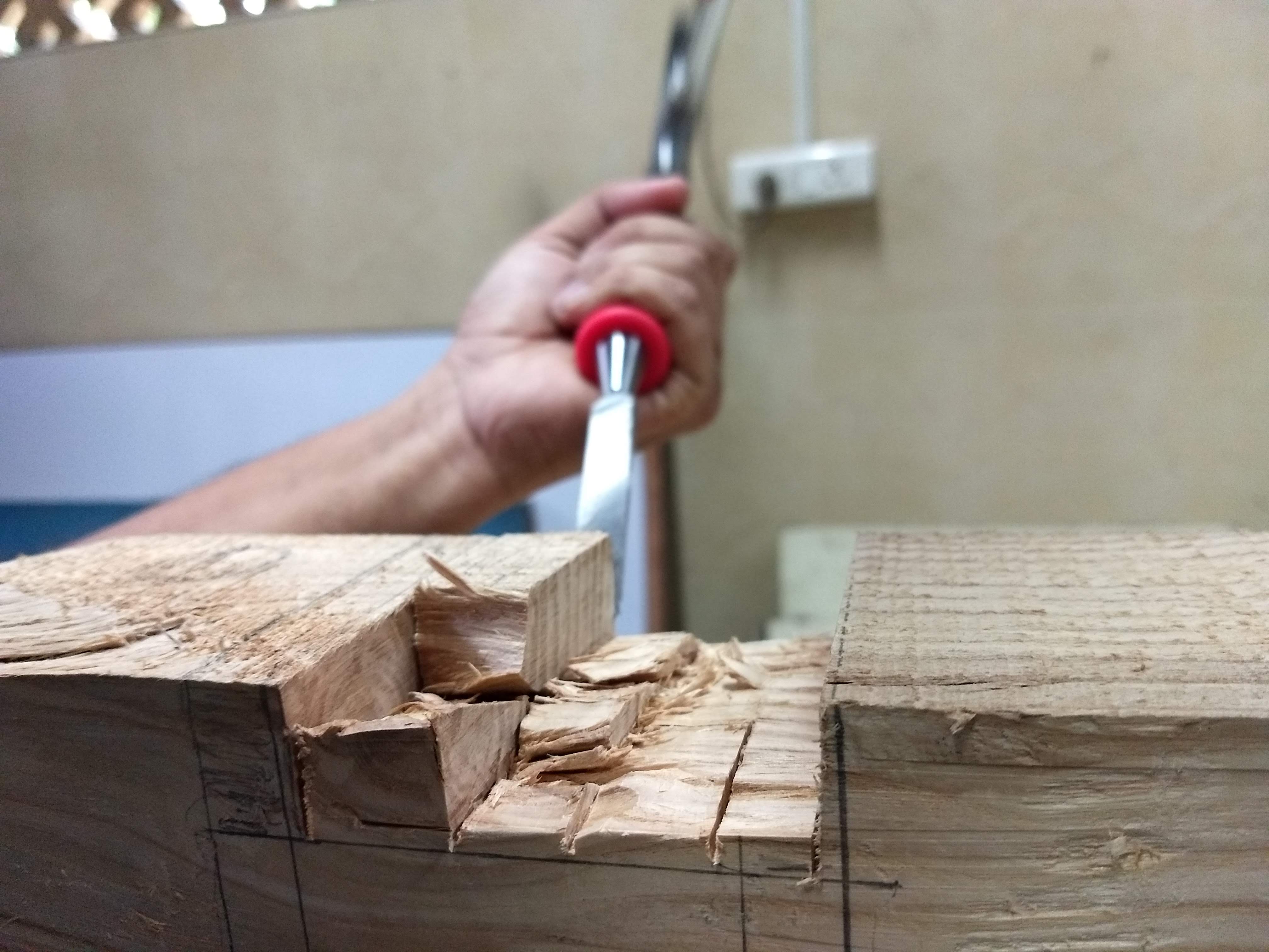
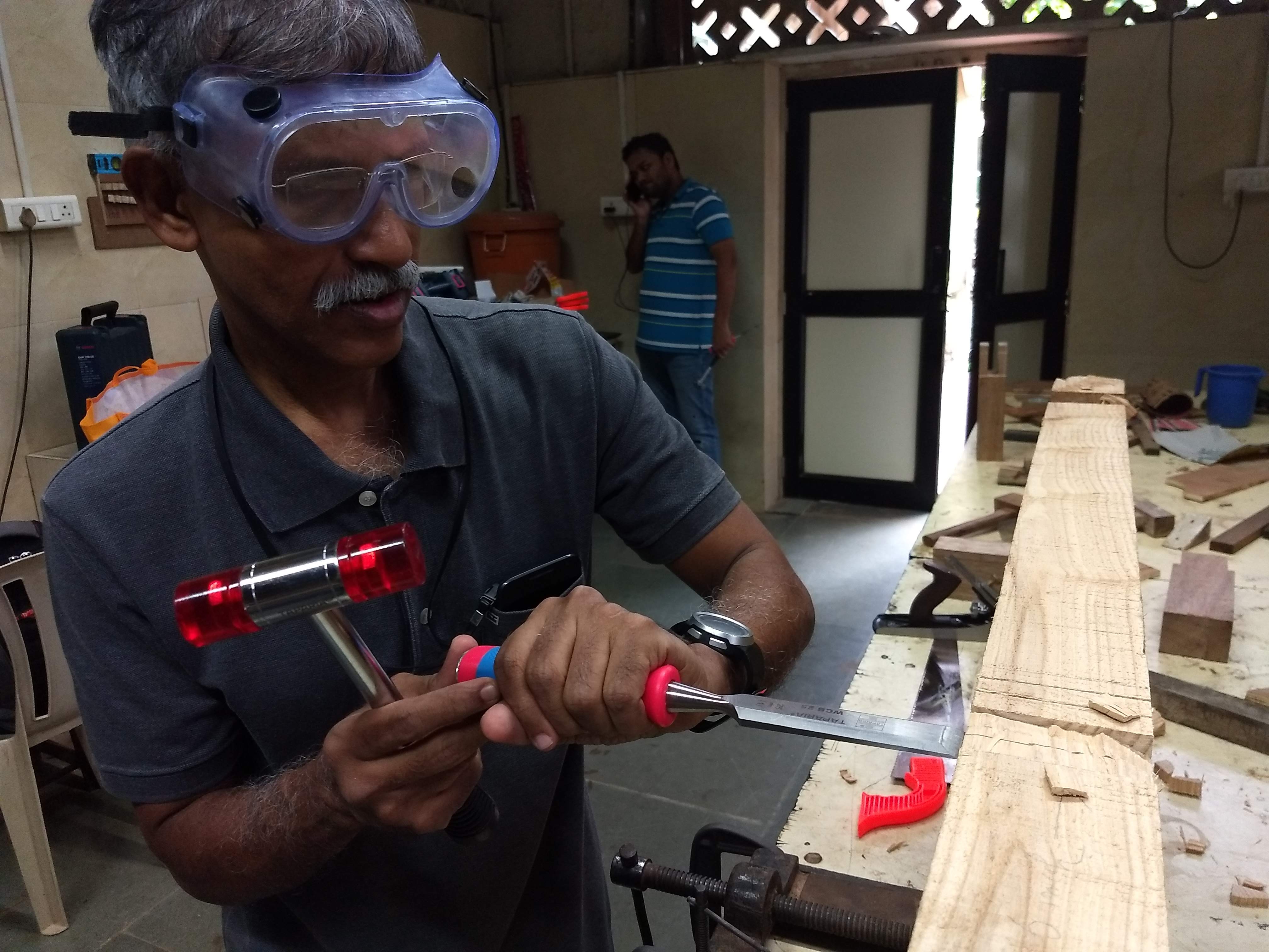
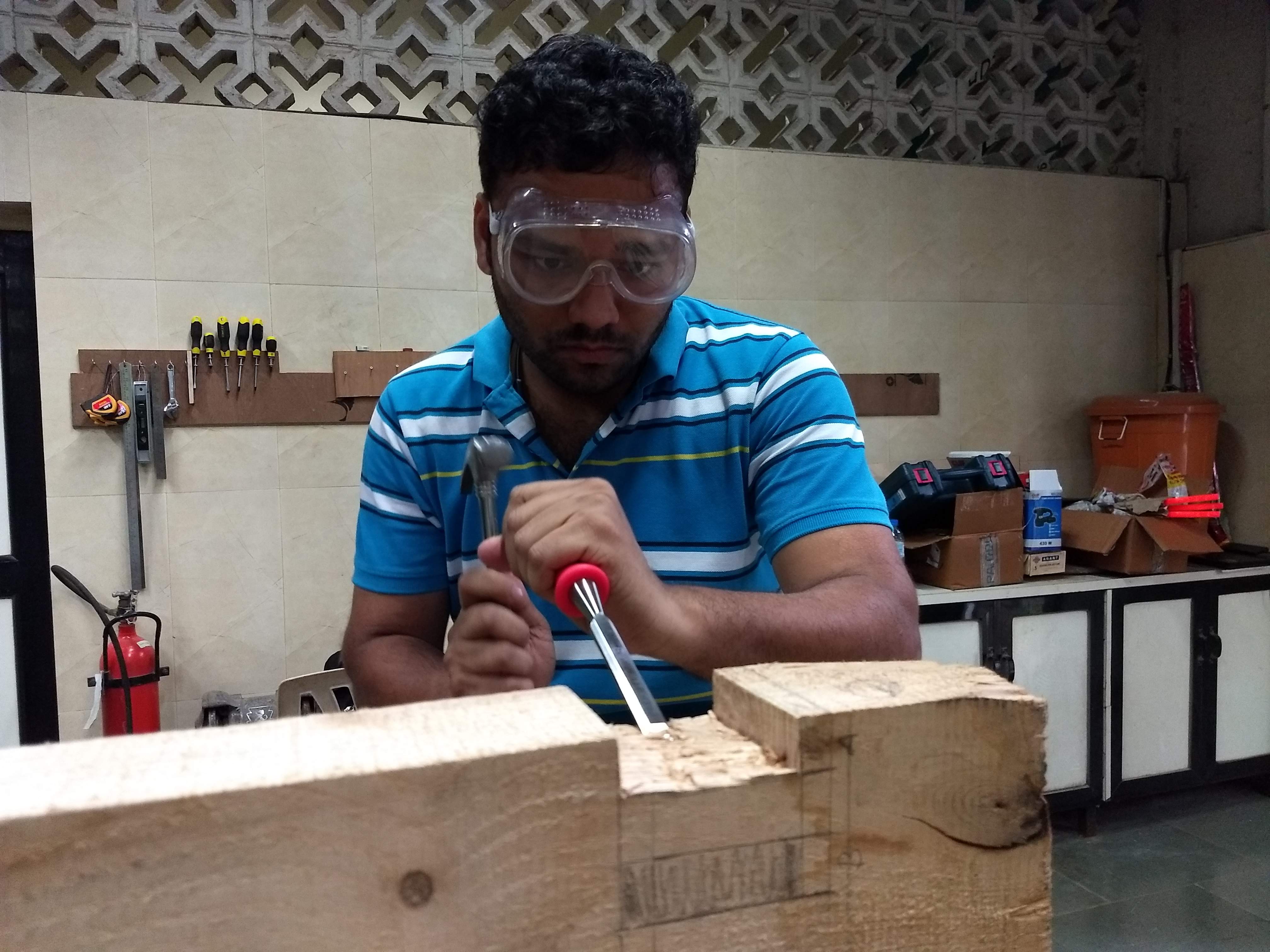
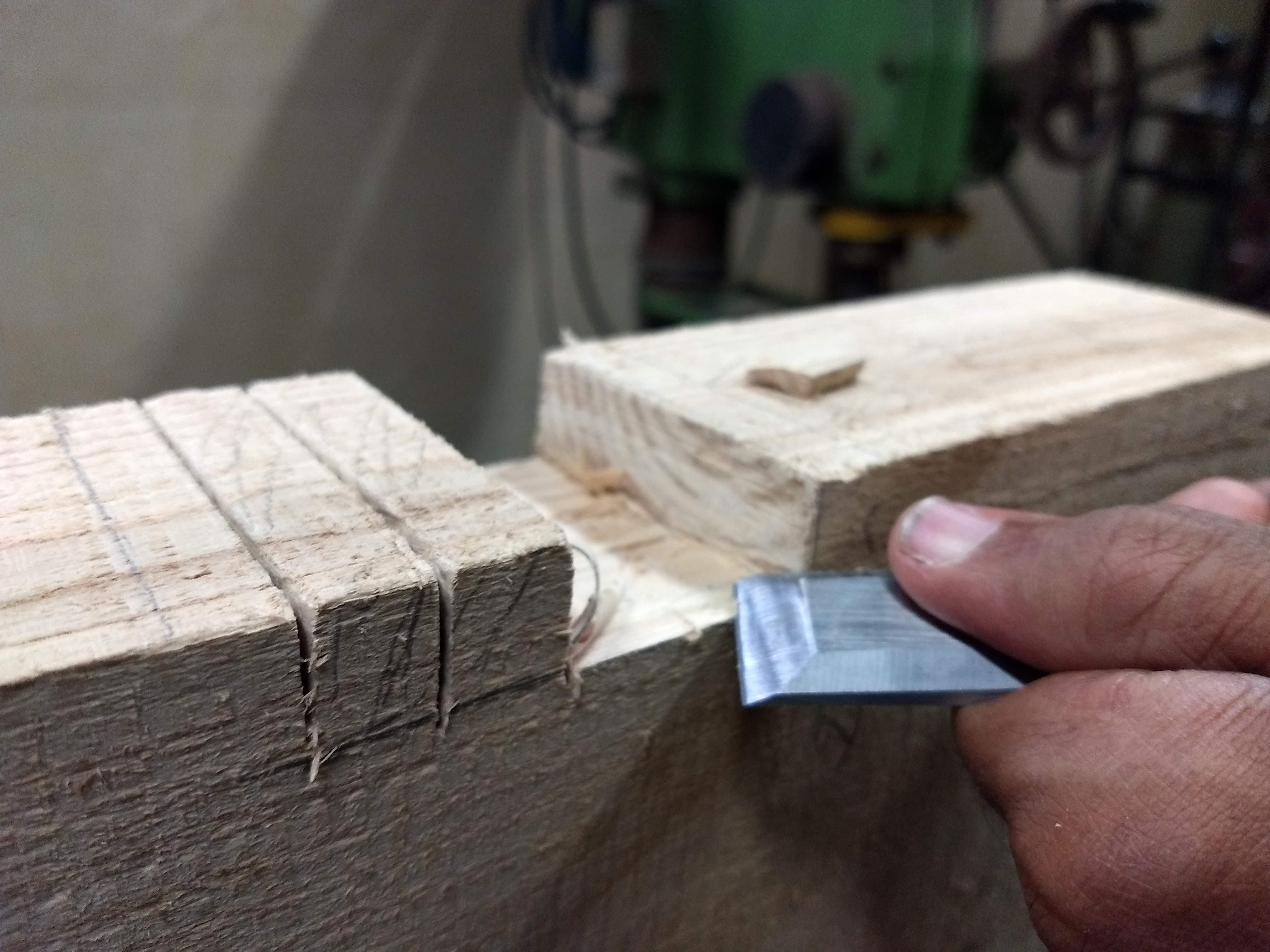
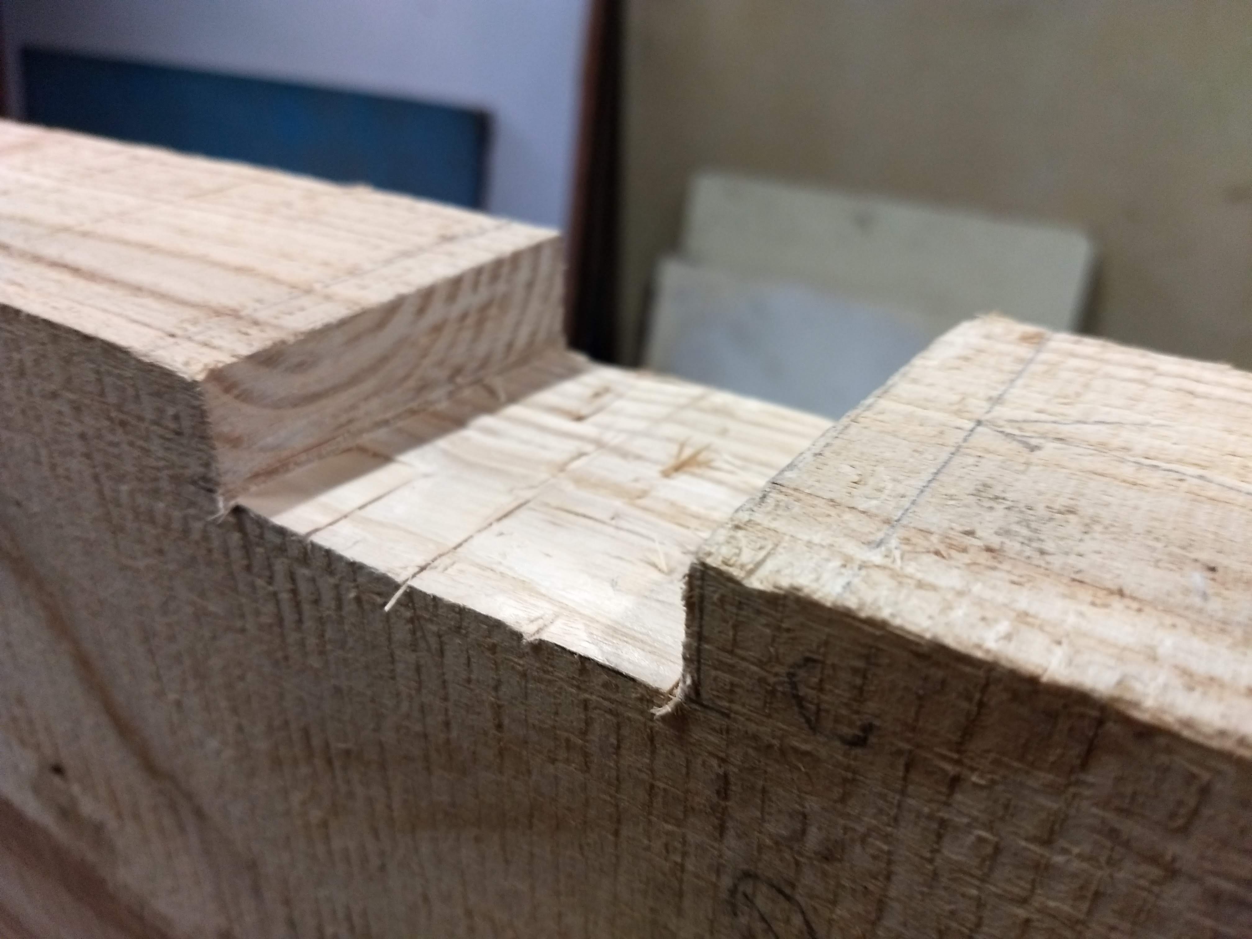
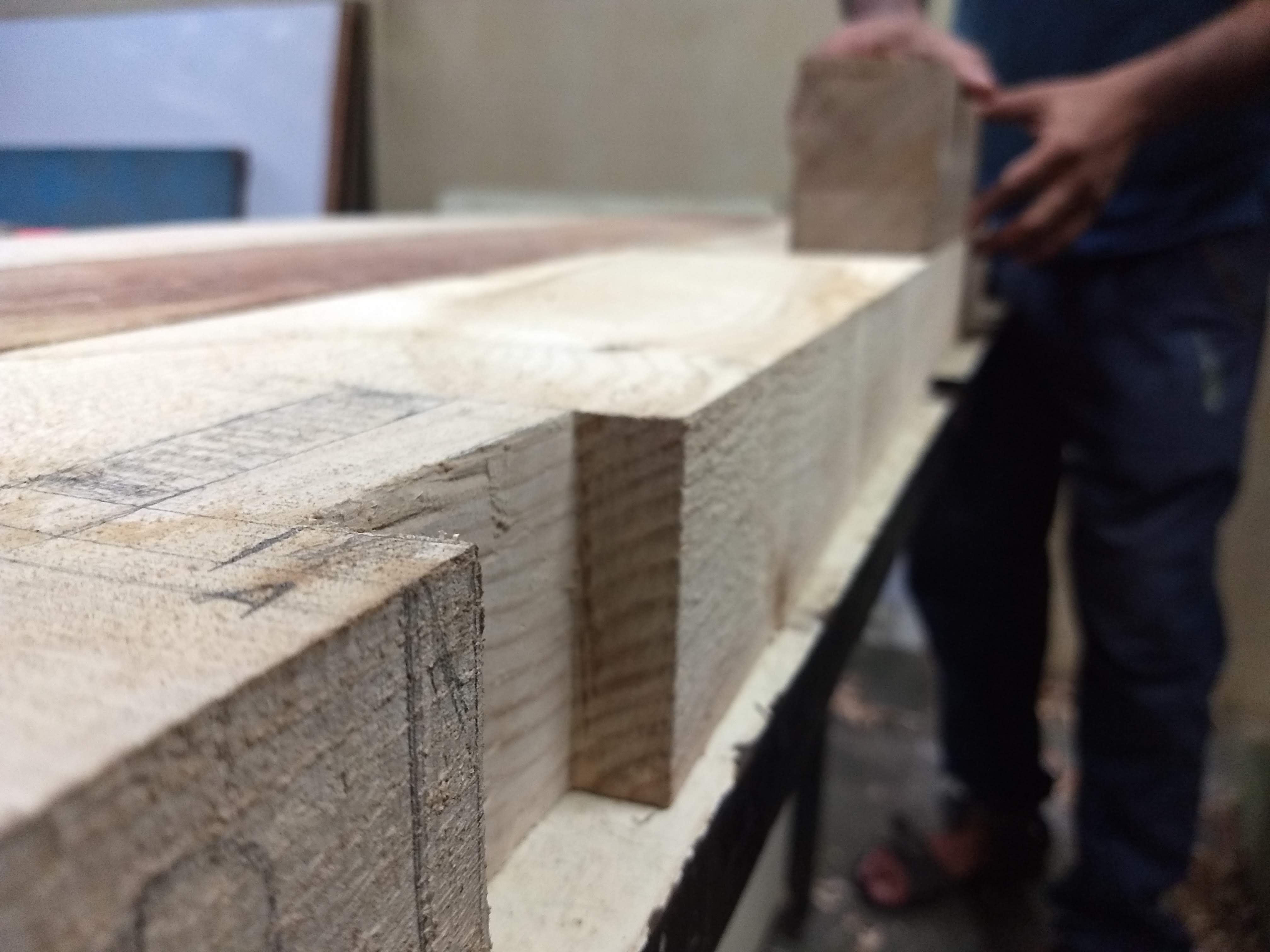
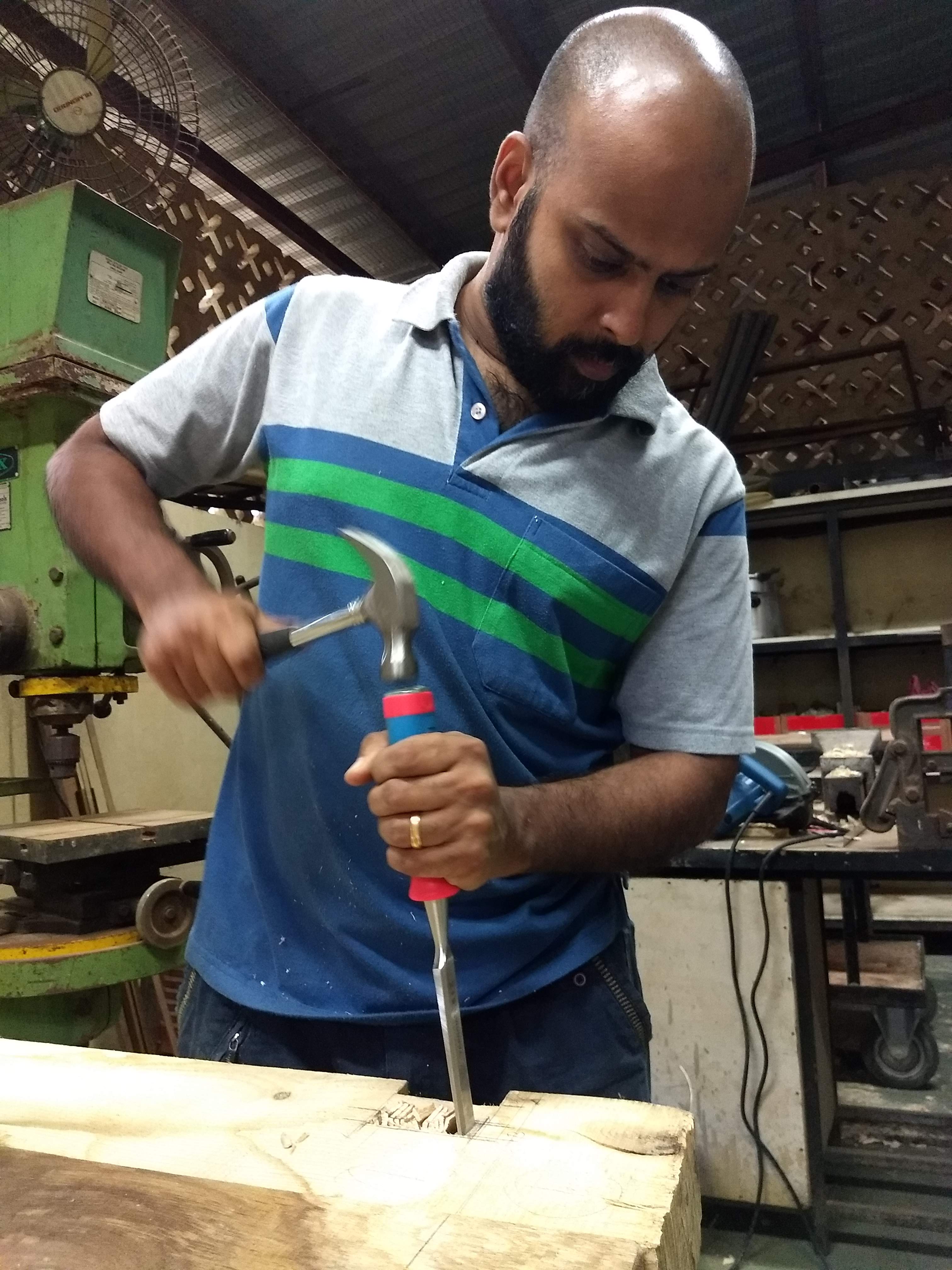
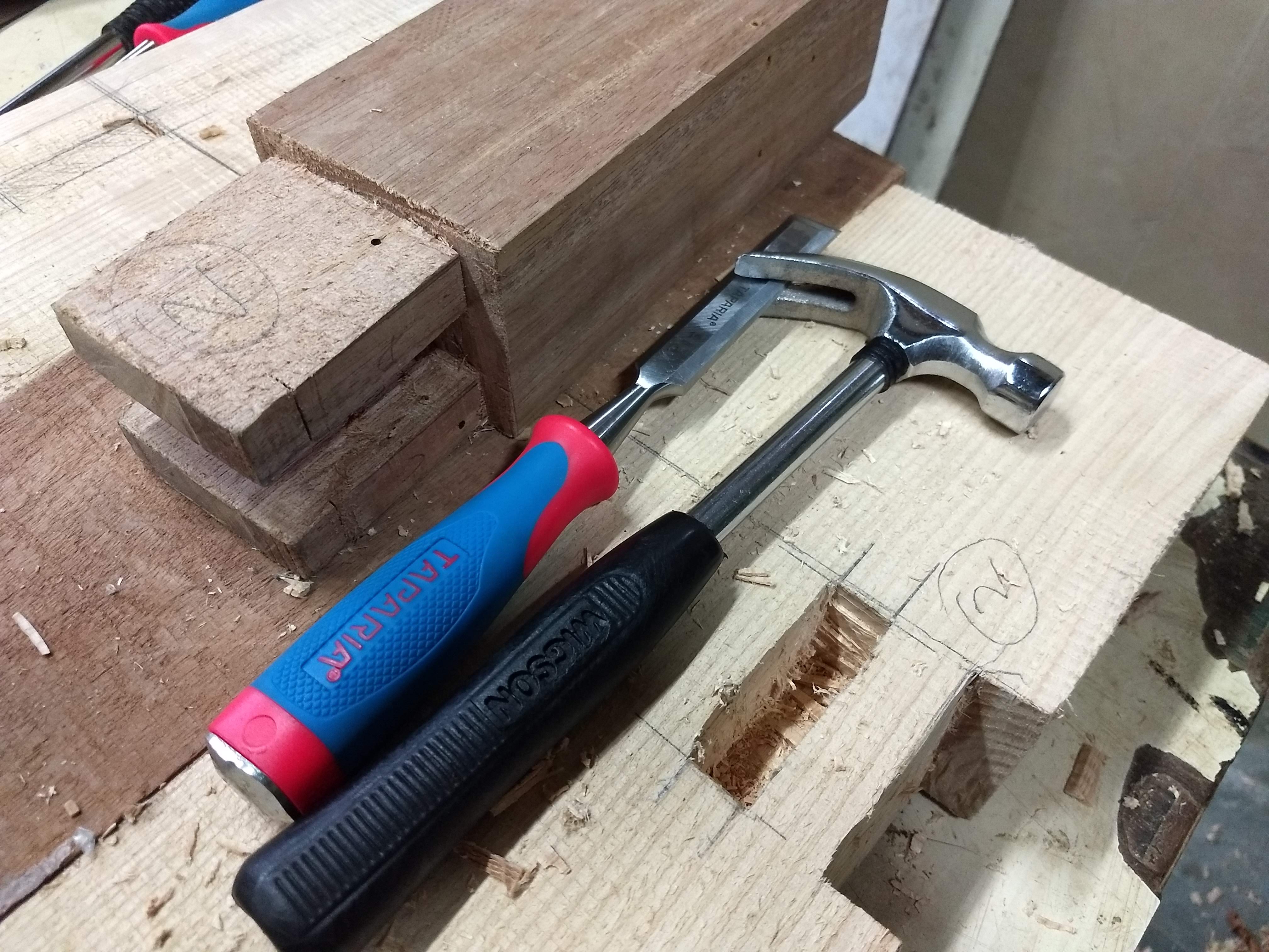
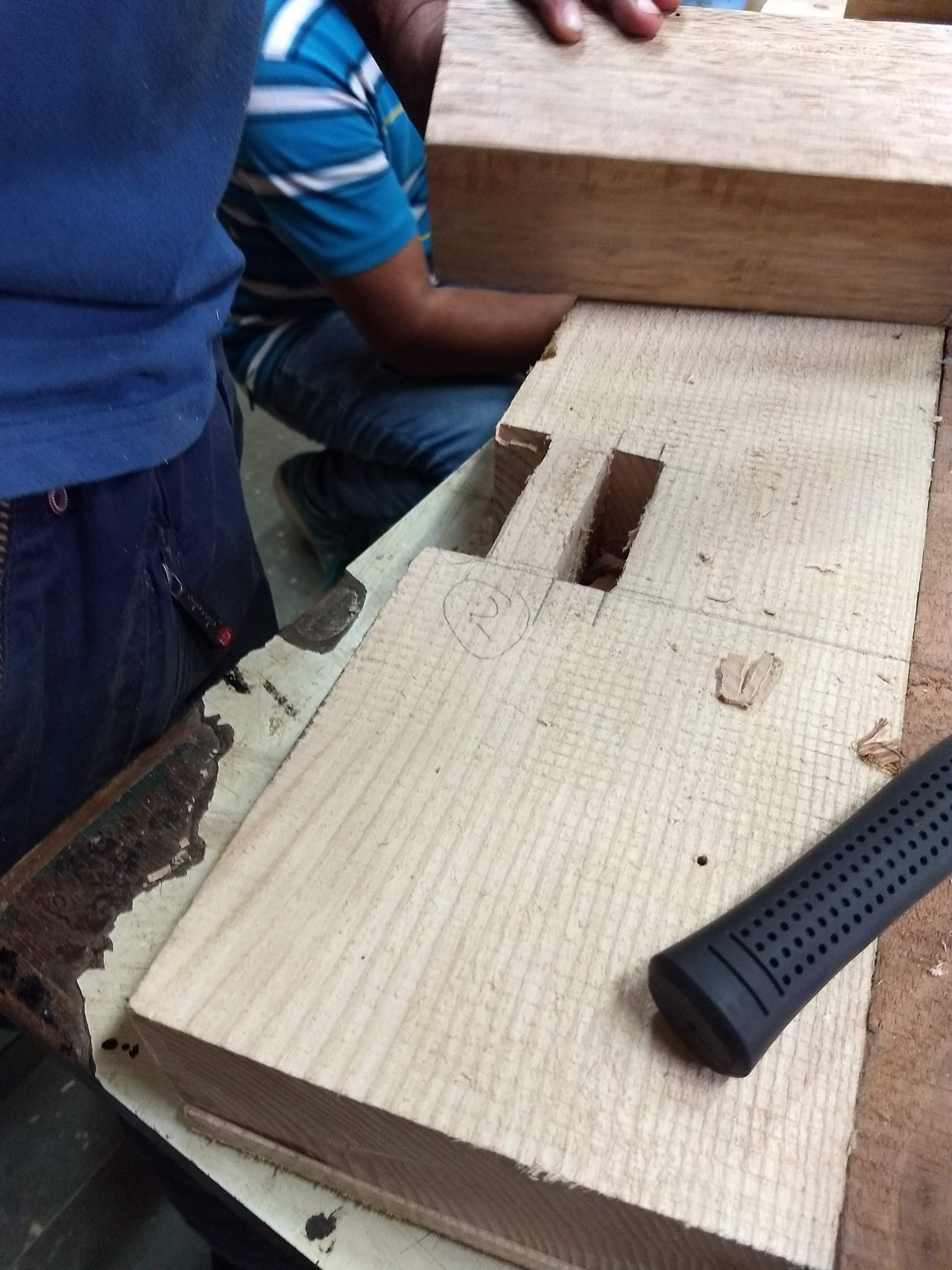
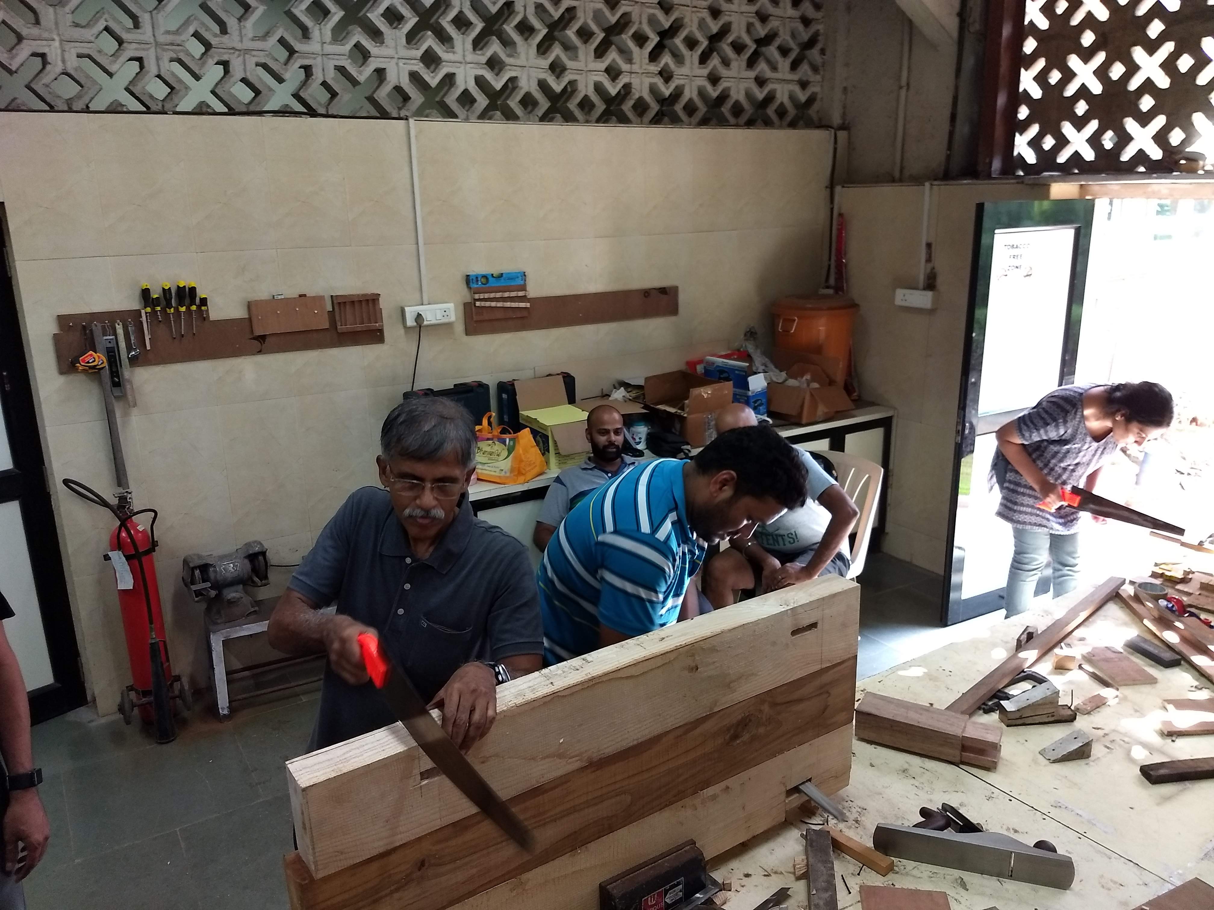
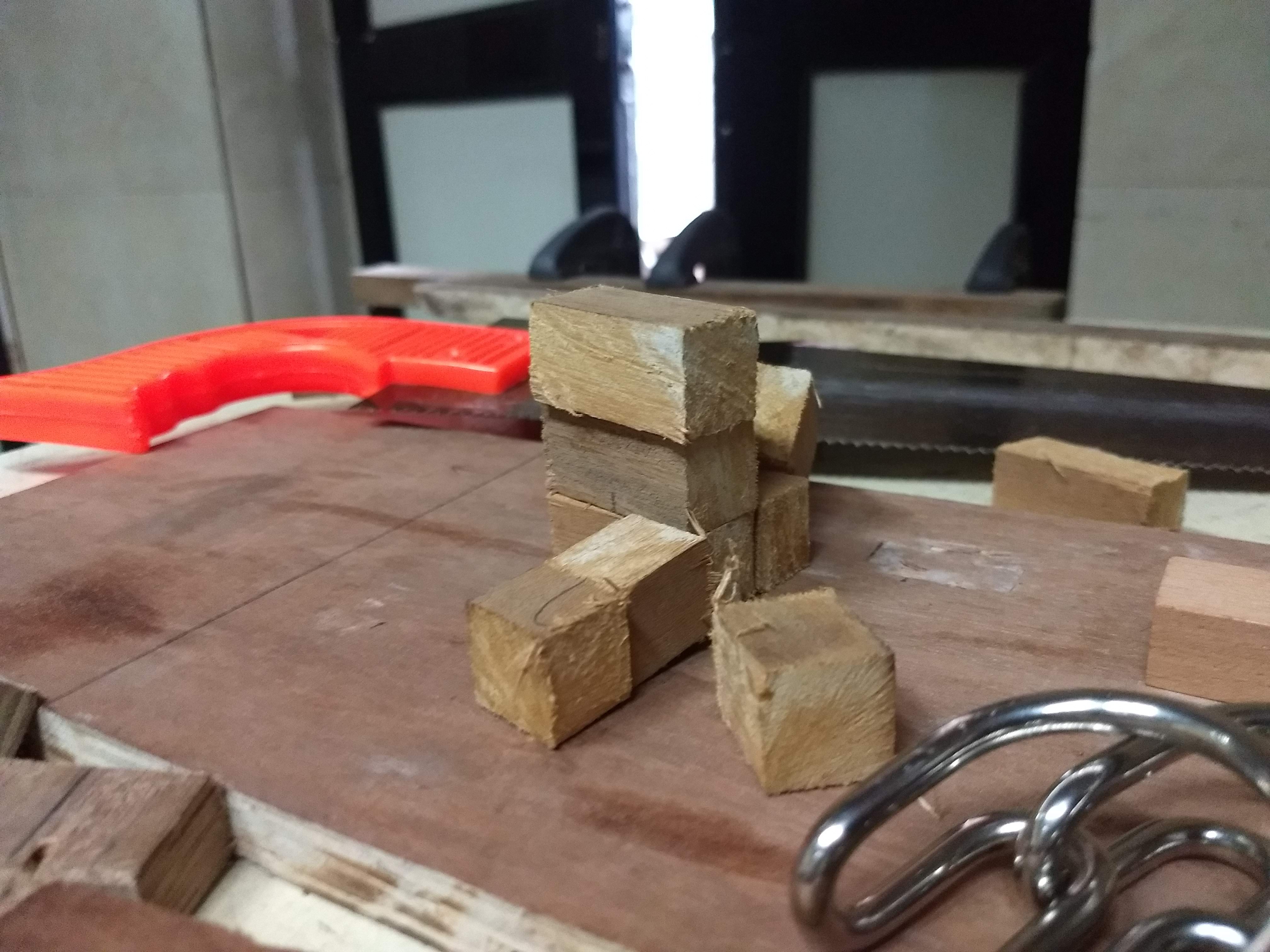
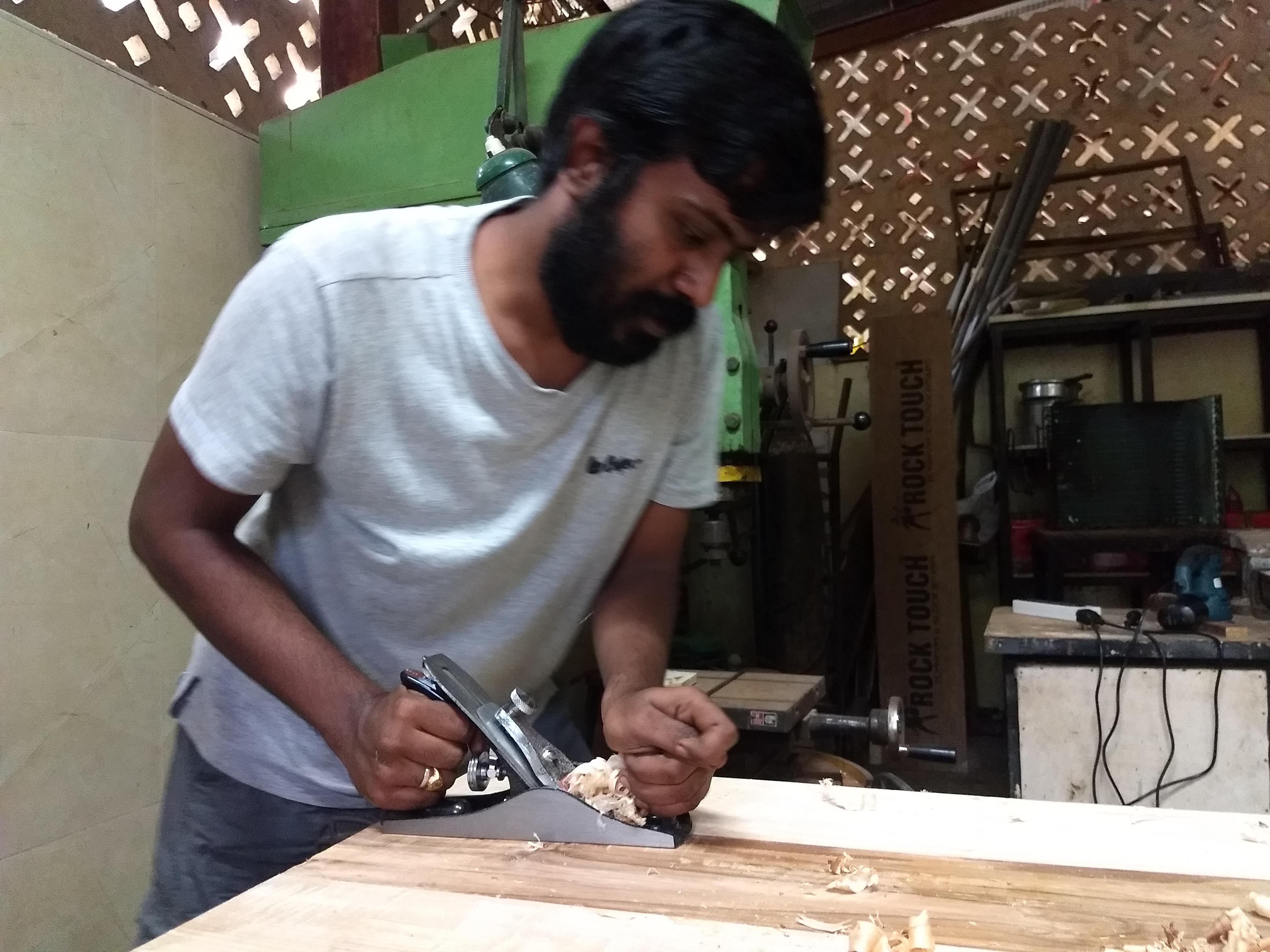
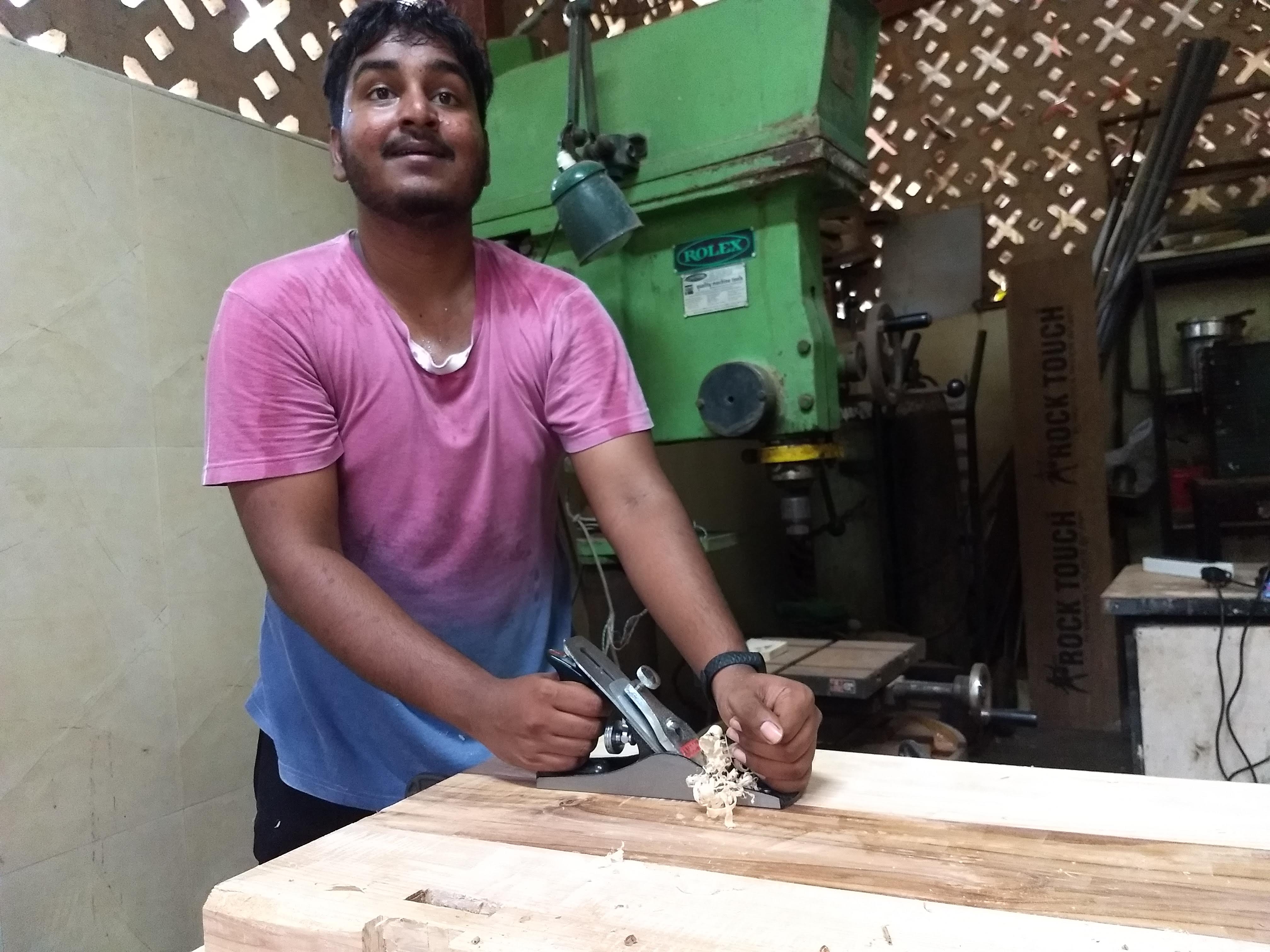
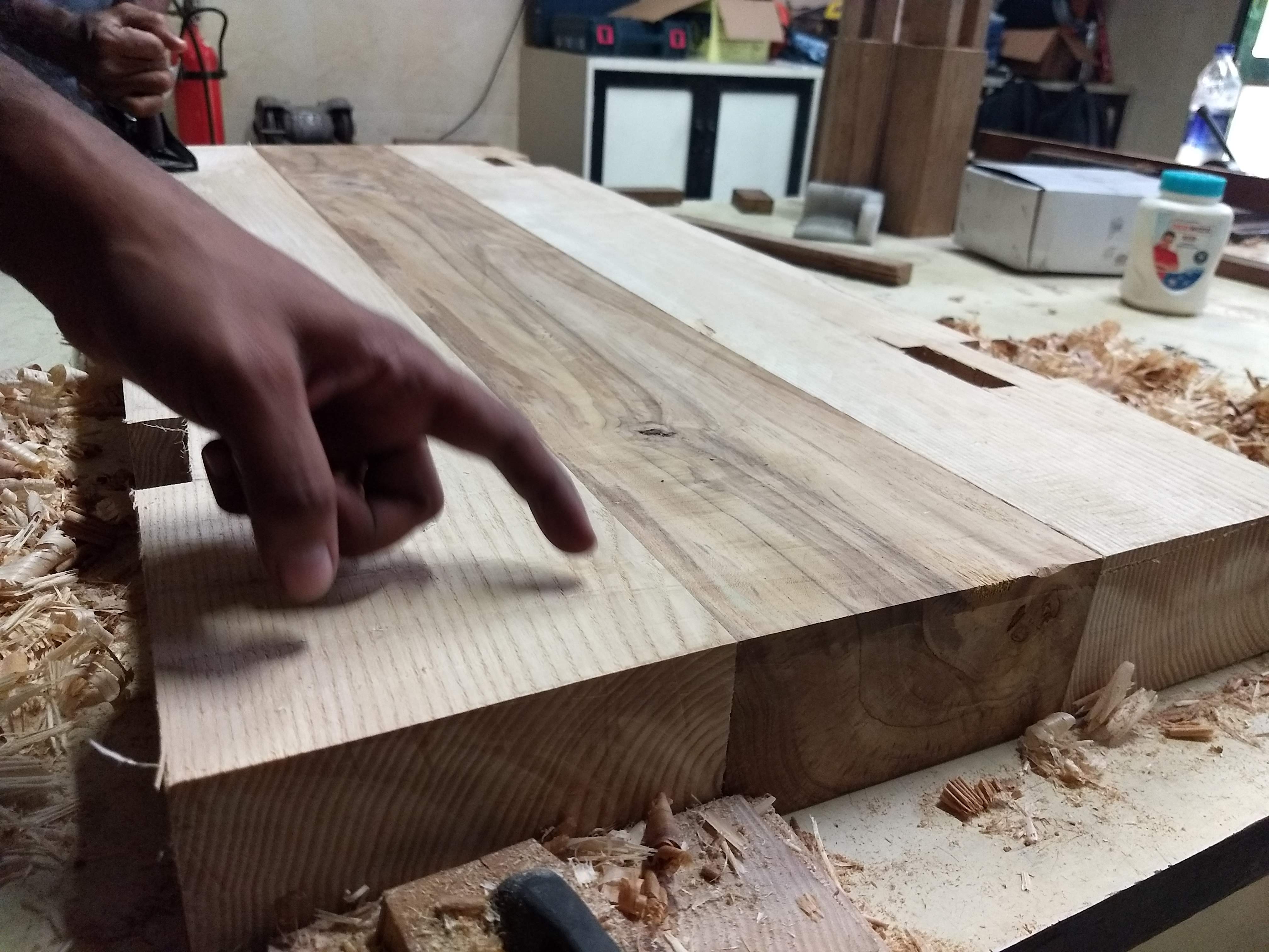
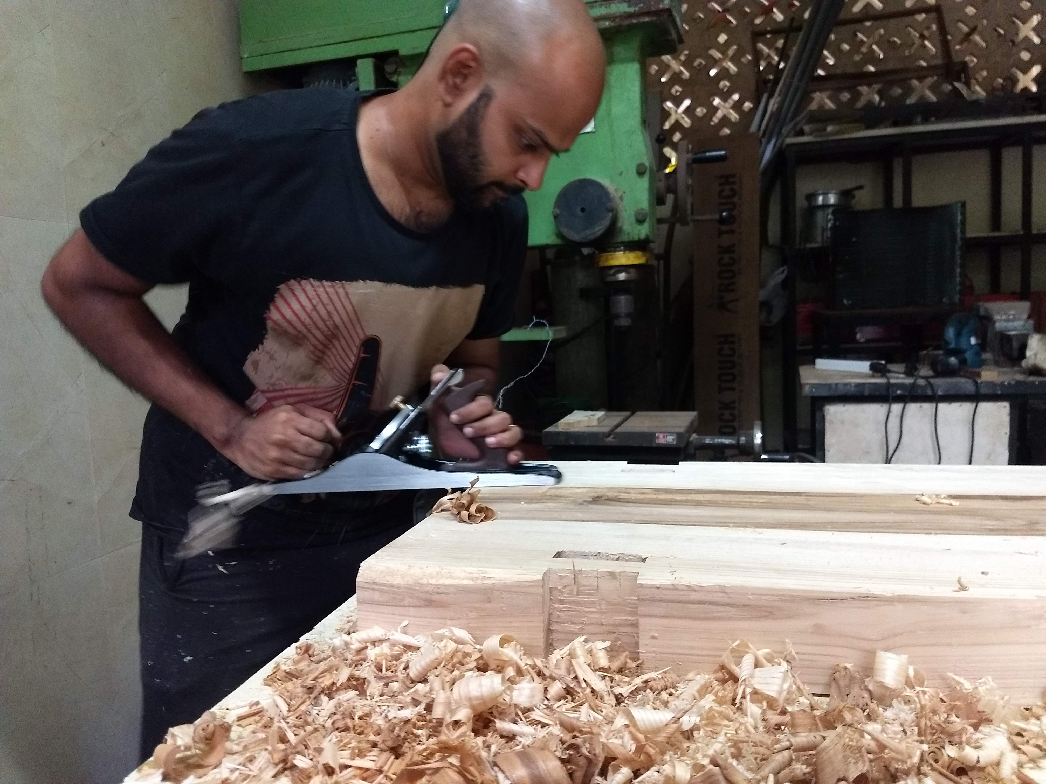
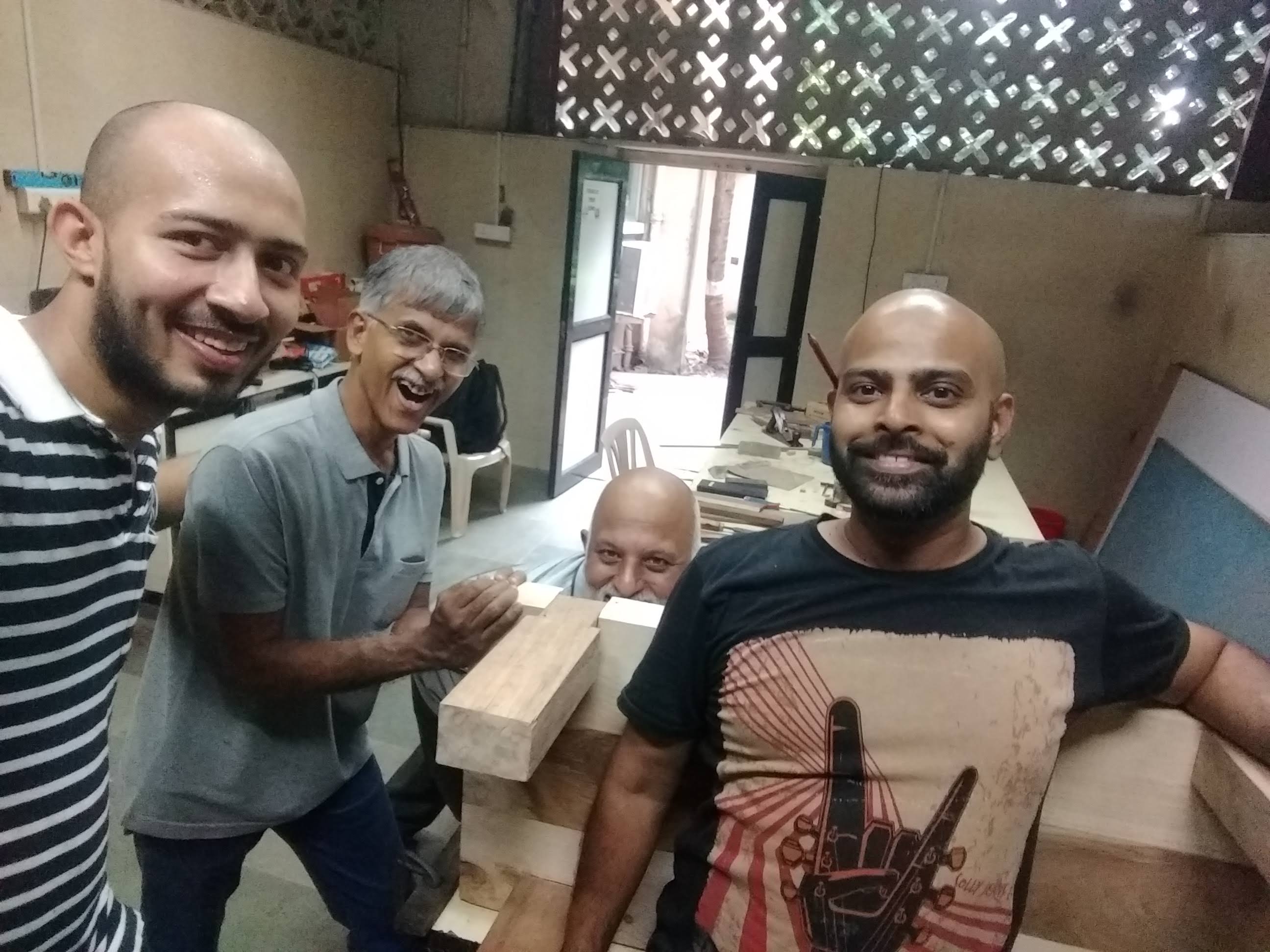
The first two holes were done using hand tools- slowly and steadily. Using a hand saw, chisel and hammer to make series of cut and then to remove the corner end .After that to make a deep cuboid shape cut of around 6 inches deep in the interior. Lastly, the interior walls needed to be smoothed so that the legs can fit in- its should neither be too tight not too loose.
Making the cut with the saw and working to remove the outside piece
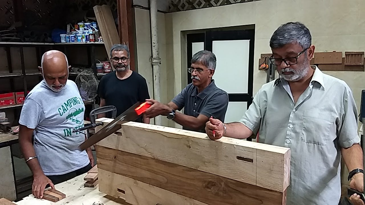
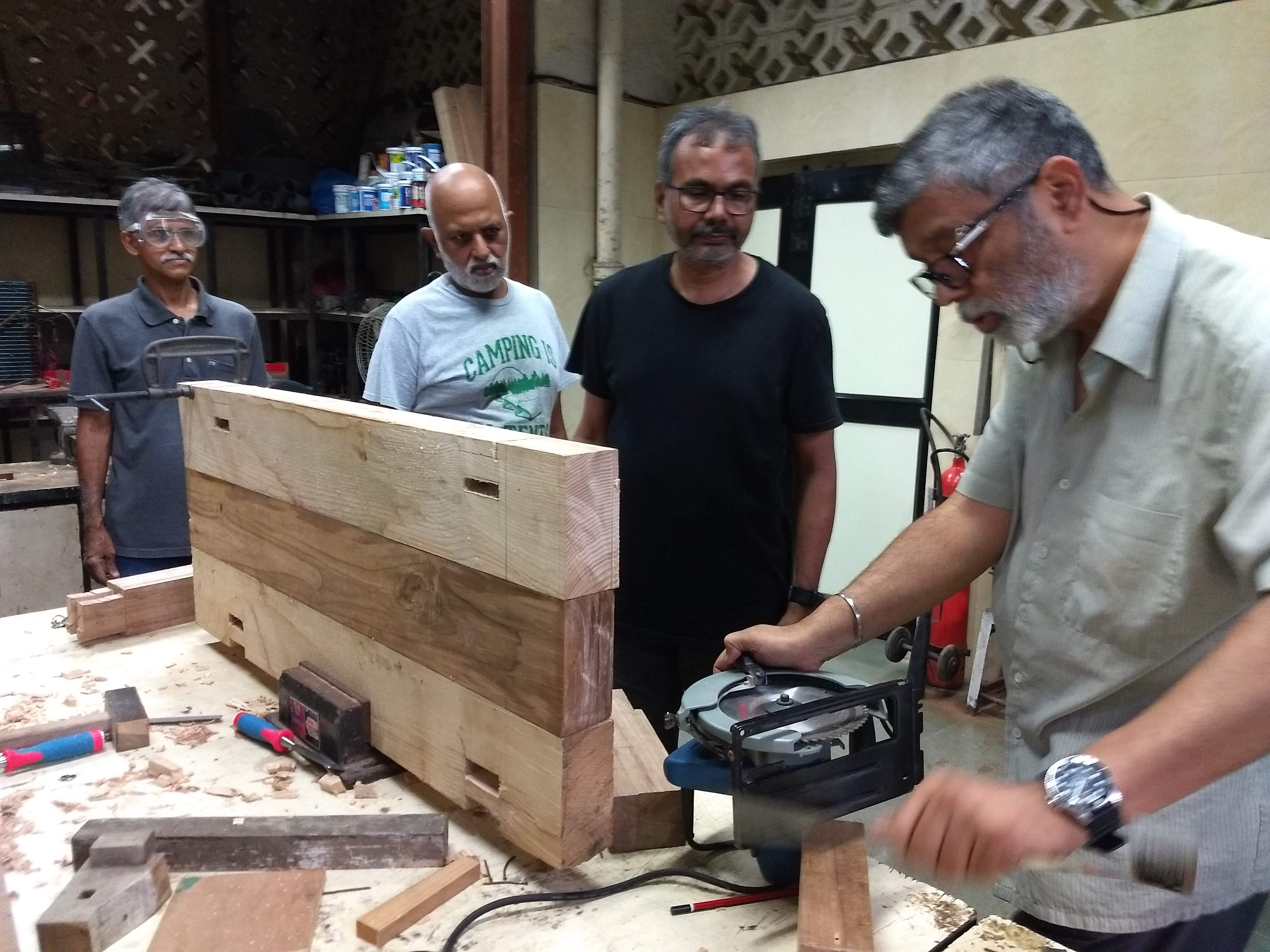
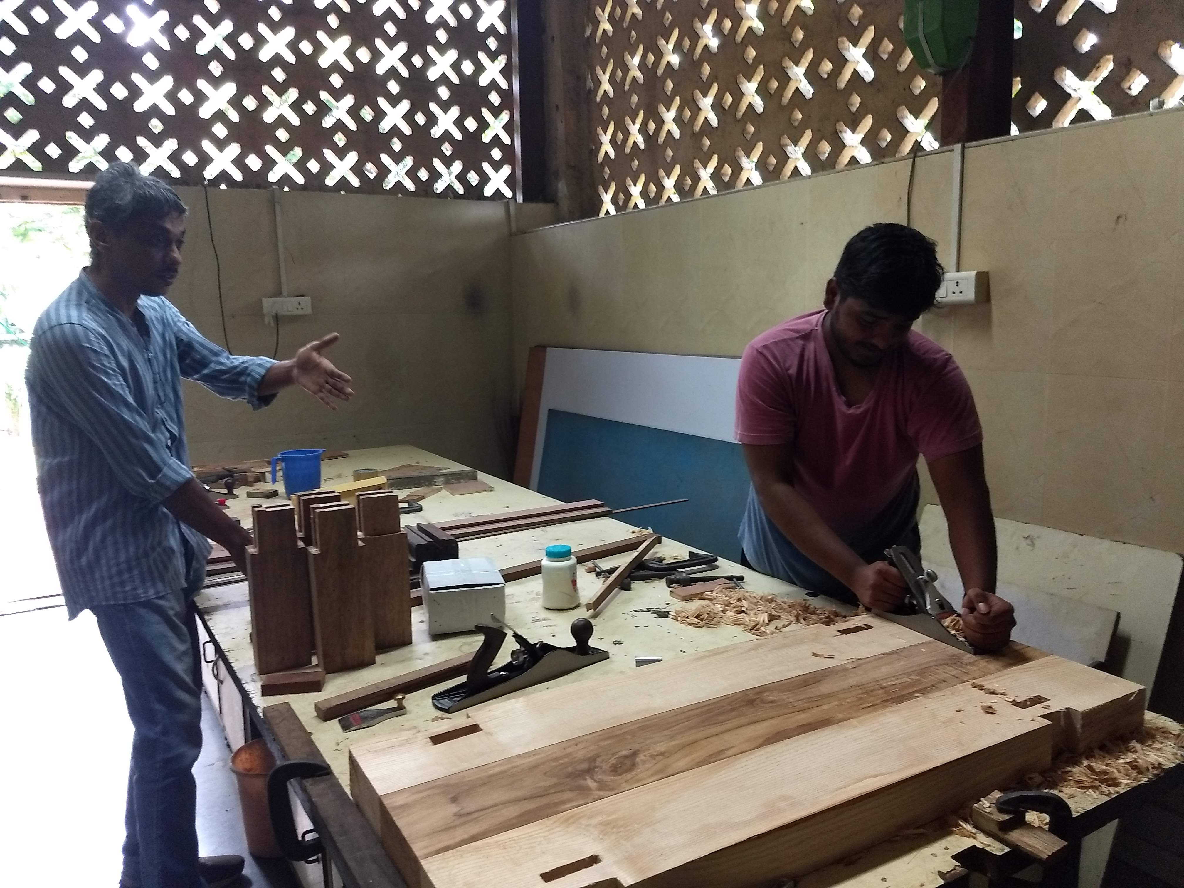
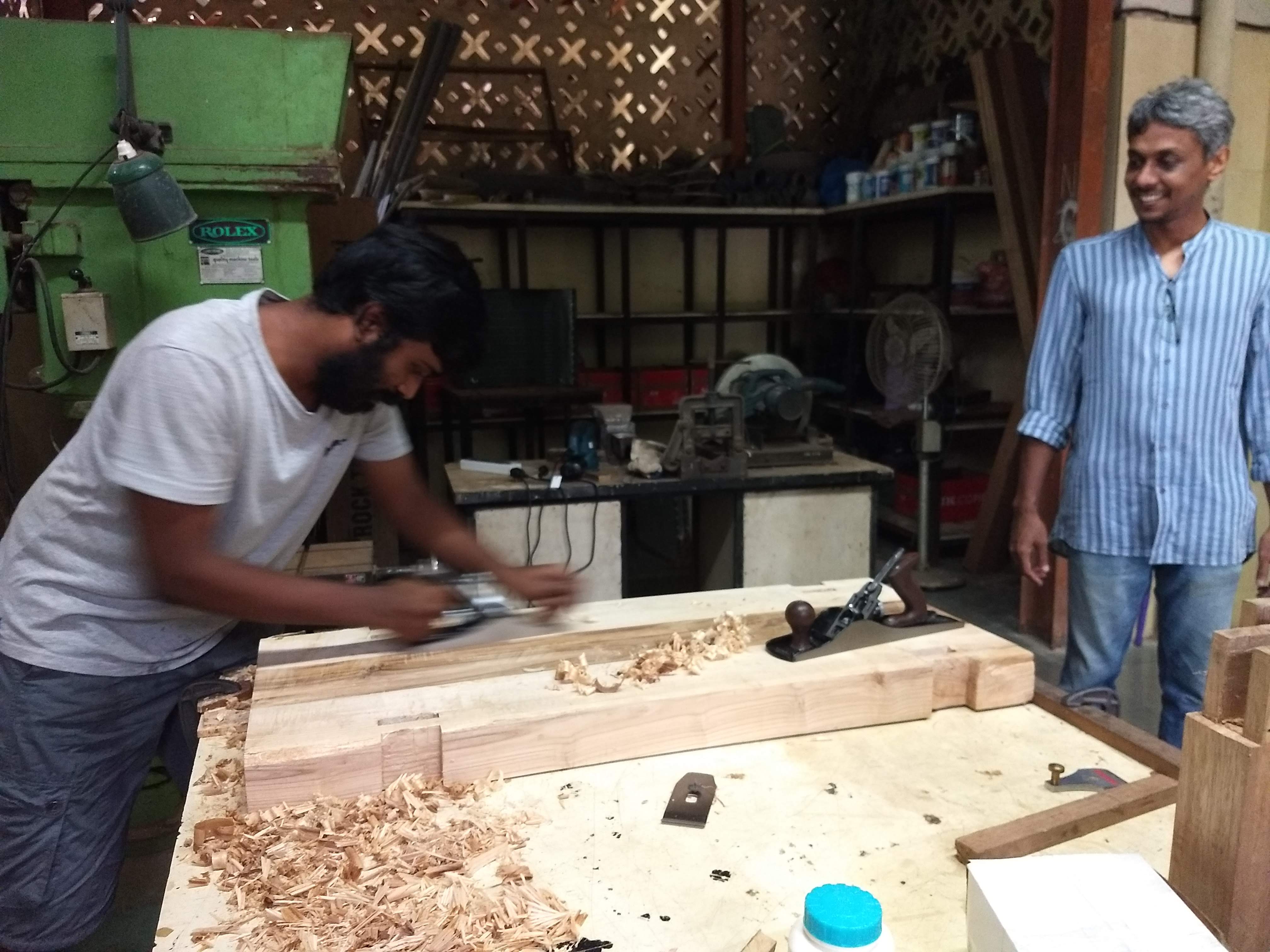
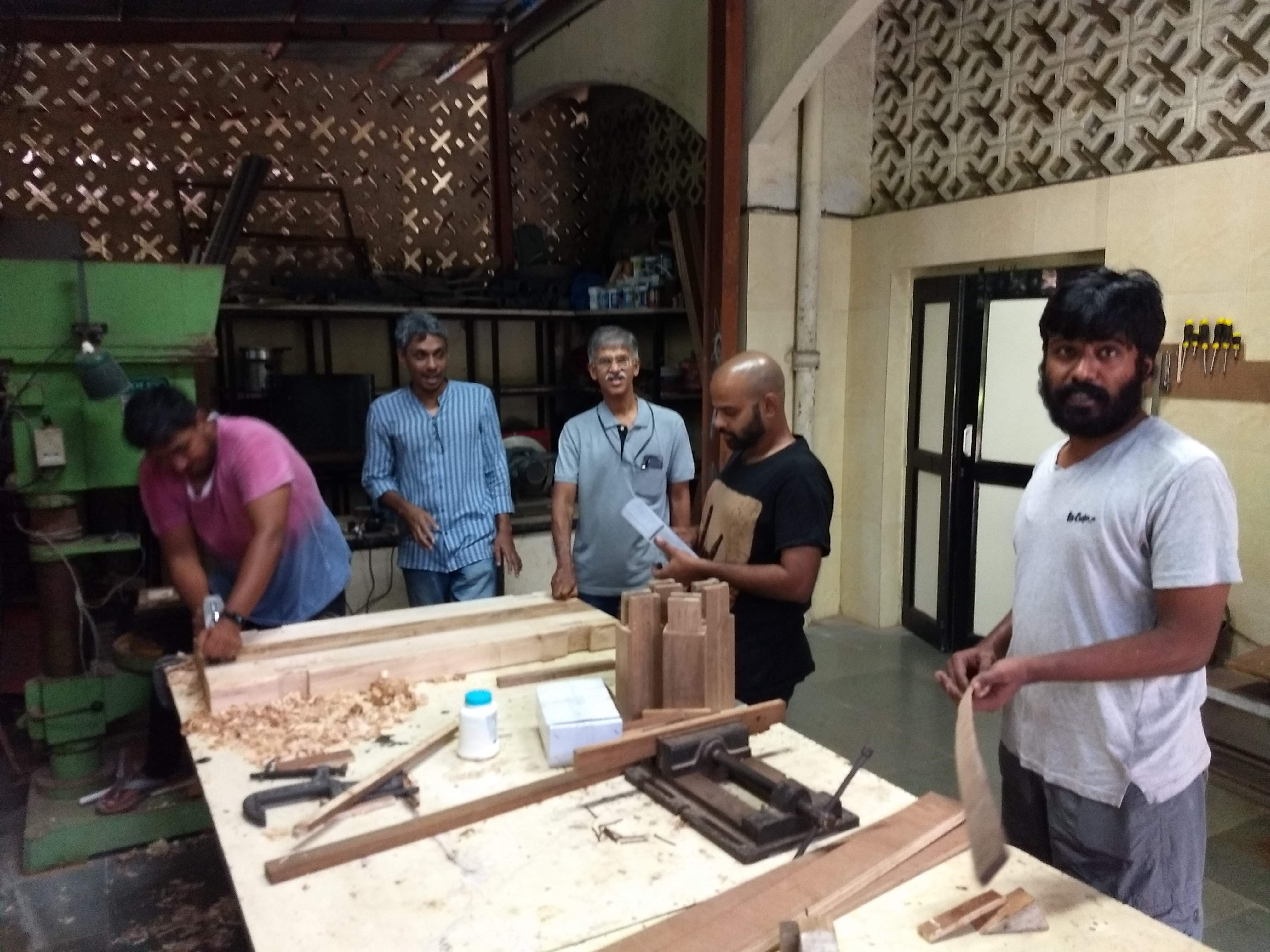
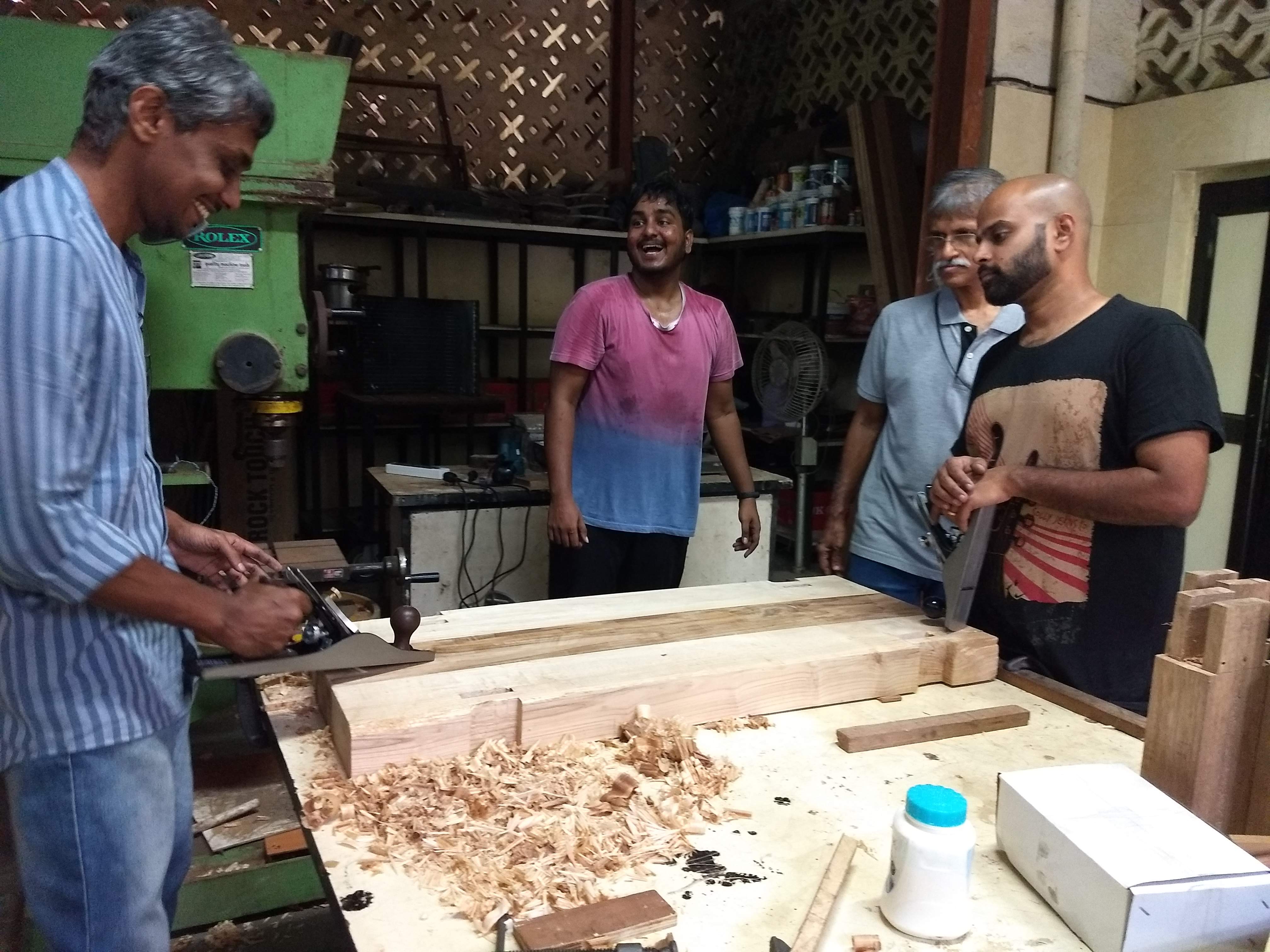
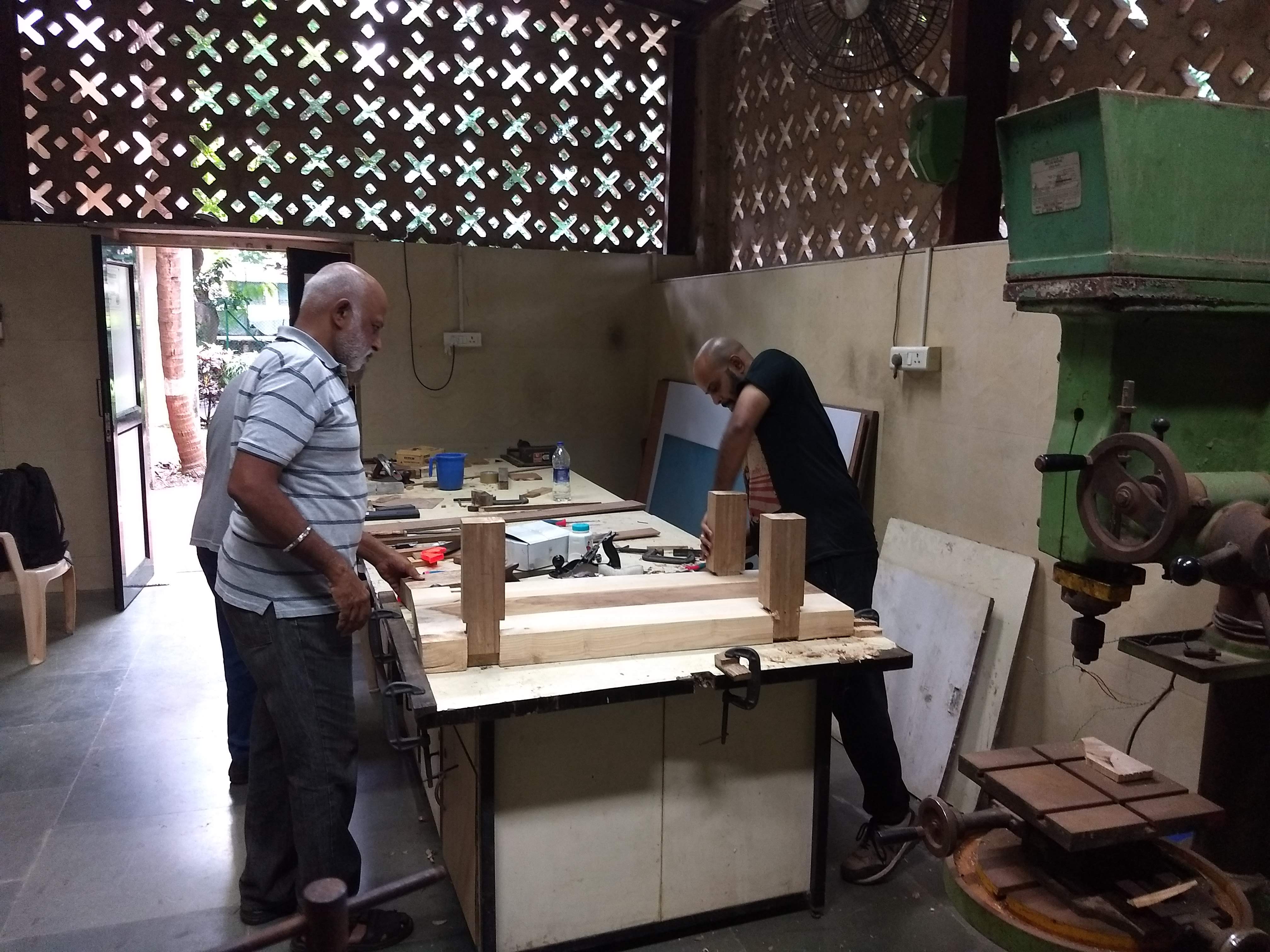
When we were left with the final slot, the team become curious to try another method to achieve the same. We used the industrial drill machine to help us with the process. Here, you can see the team experimenting with both electric circulars saw to make a series of cut initially, and later on using a drill press to make the interior cuboid.
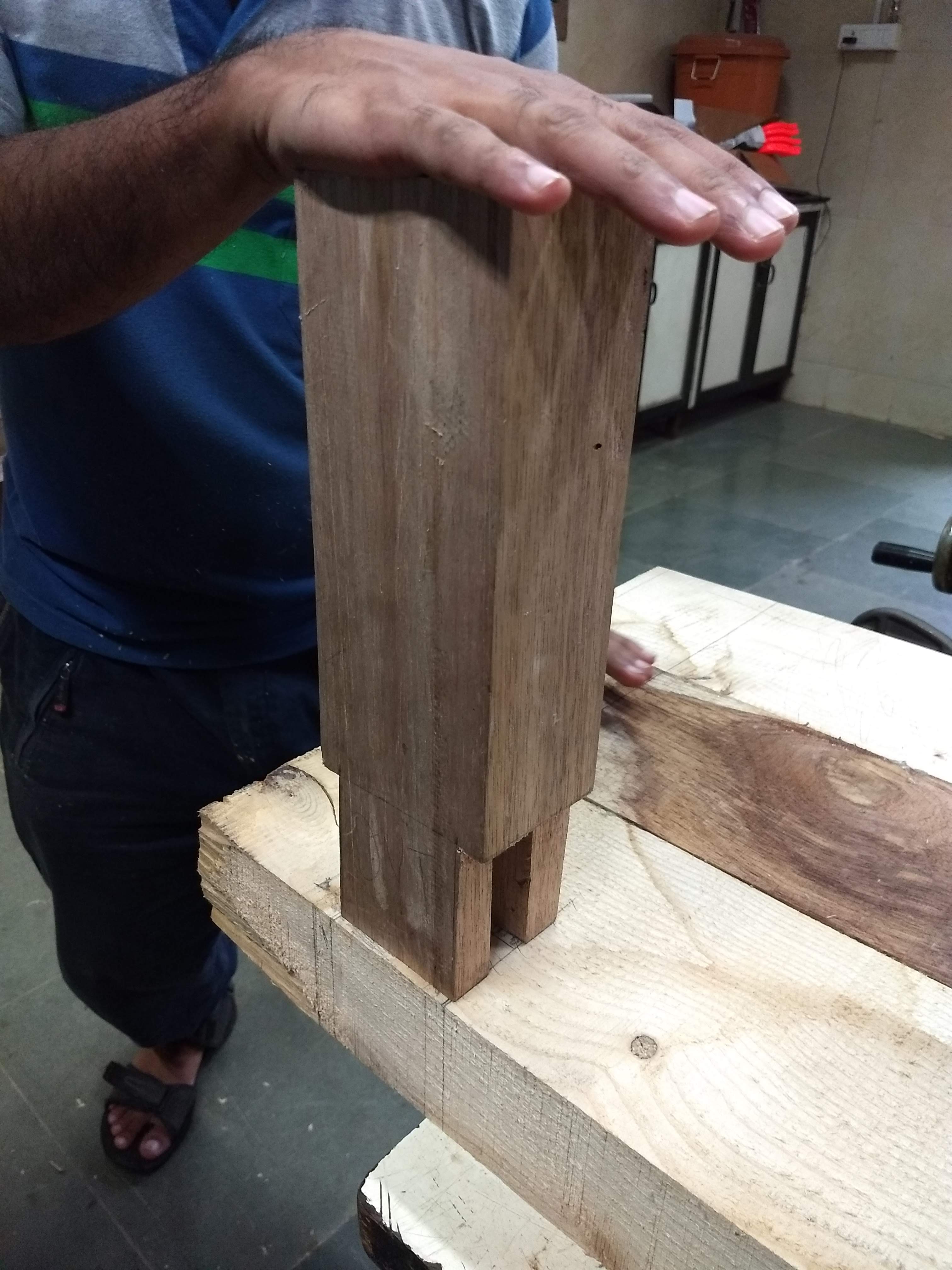
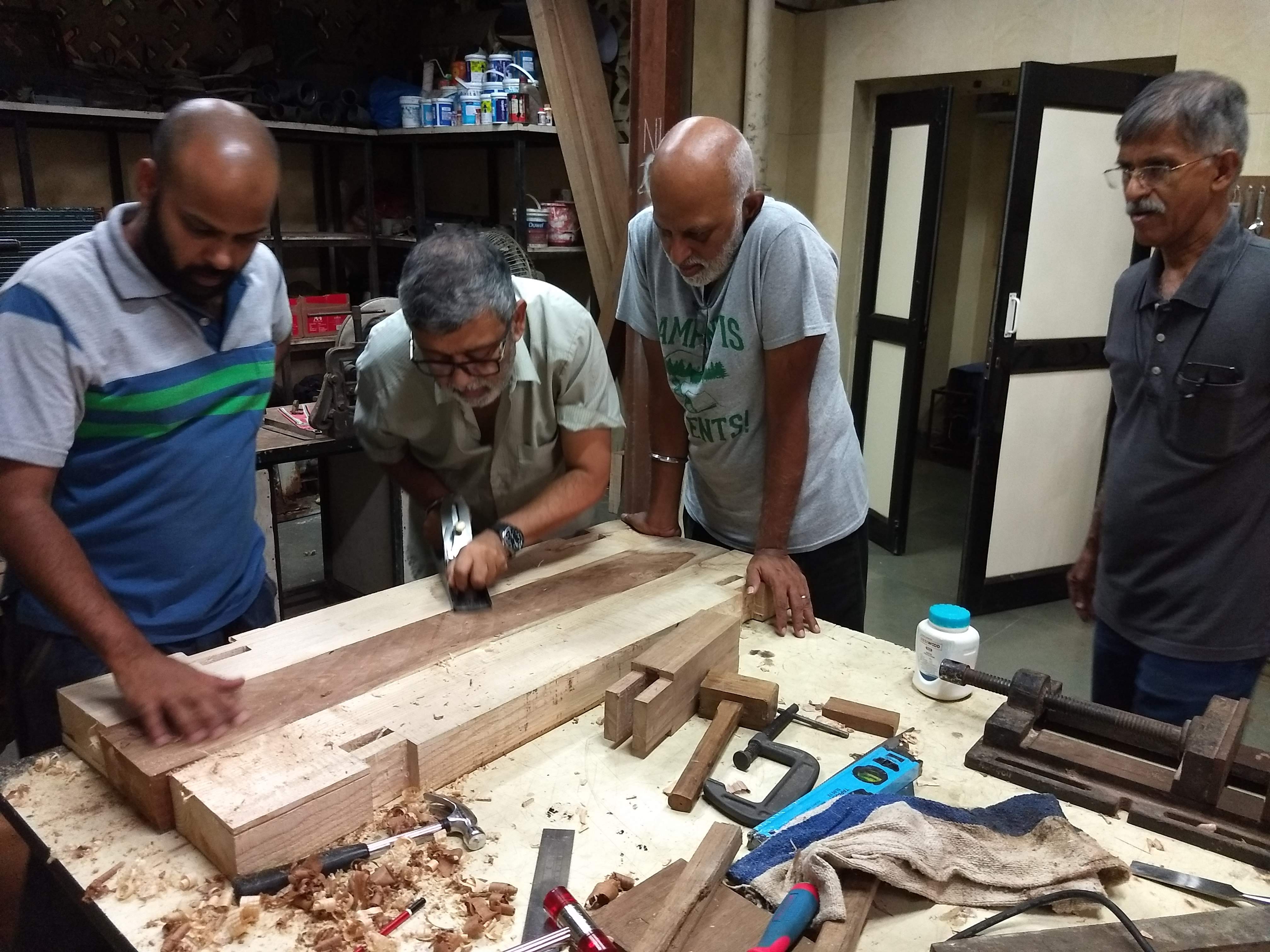
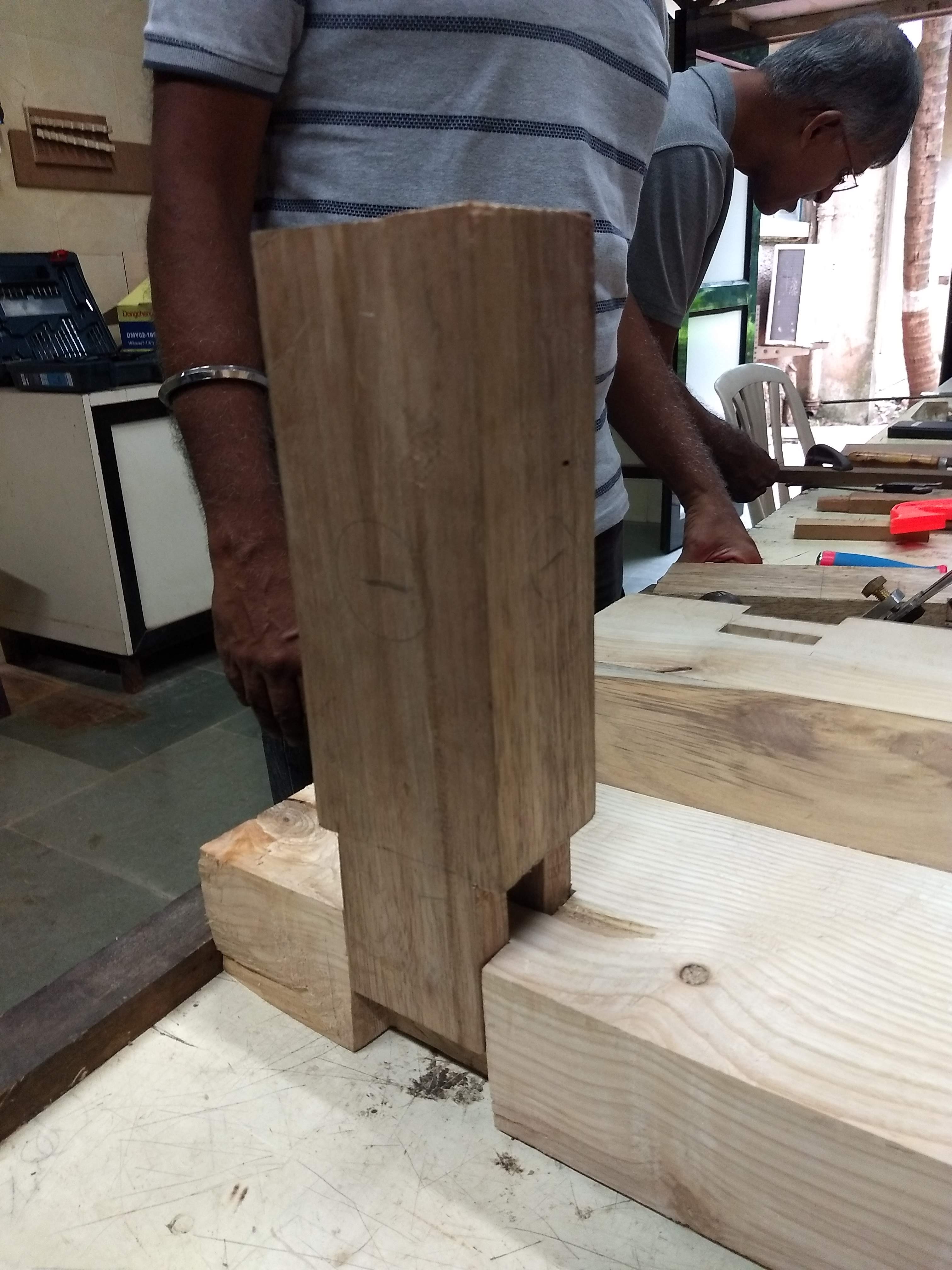
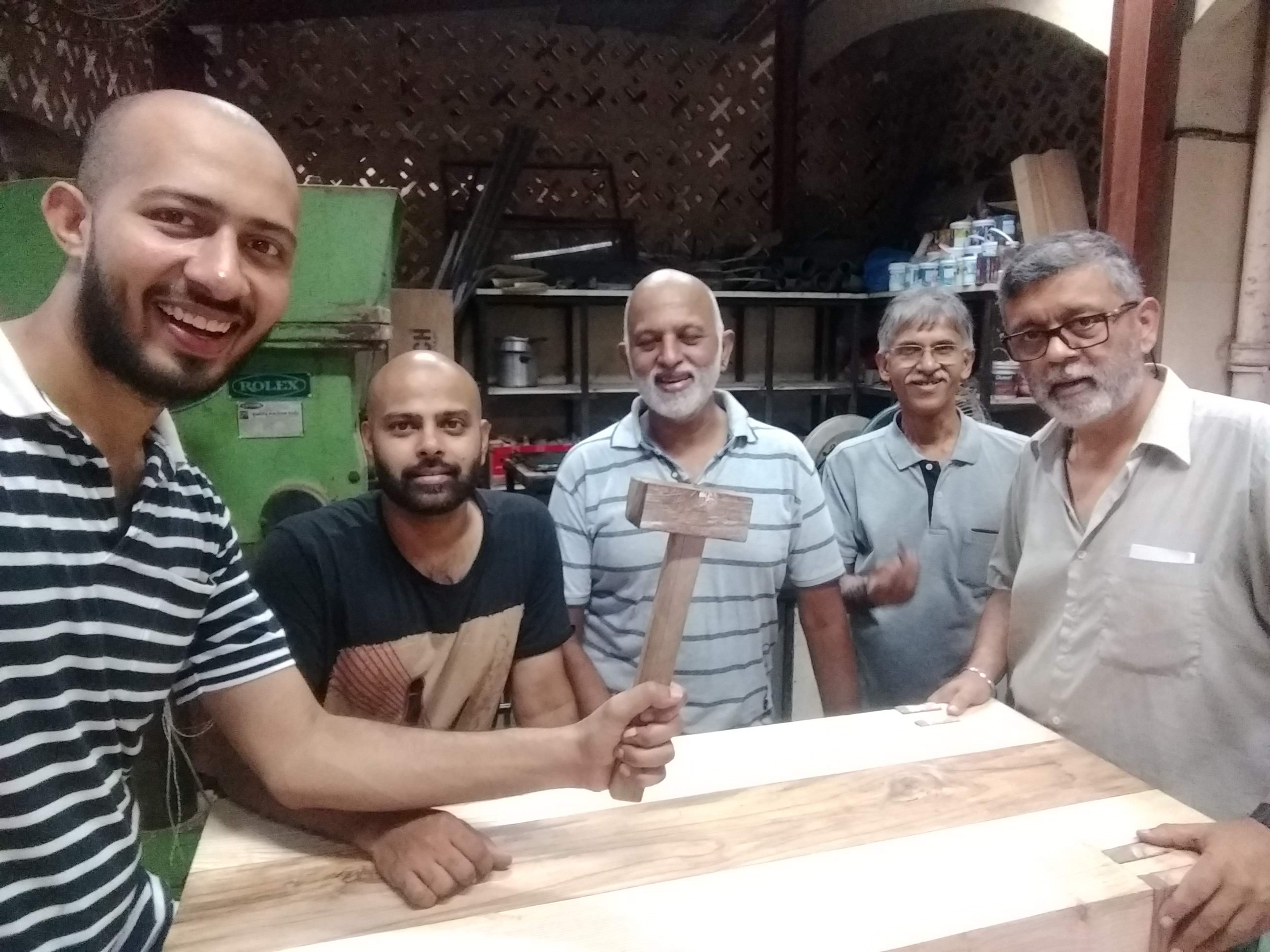
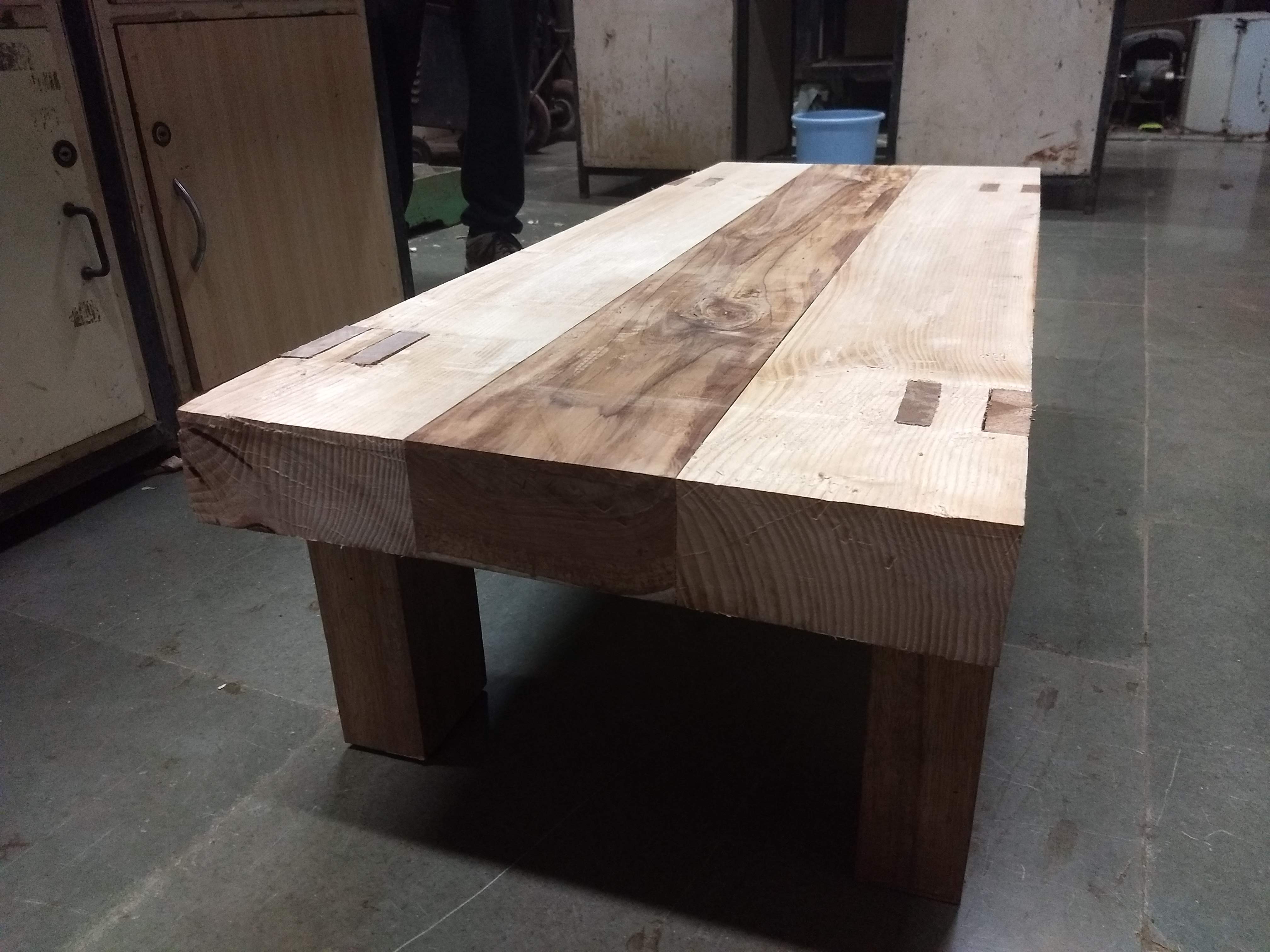
In the second half, the necessary adjustments were made so that the legs fit in the grove properly. This indeed is a meticulous job and requires a lot of patience, estimation, and skill. Finally, when the legs were plugged in, the extra part on top was removed and smoothed.
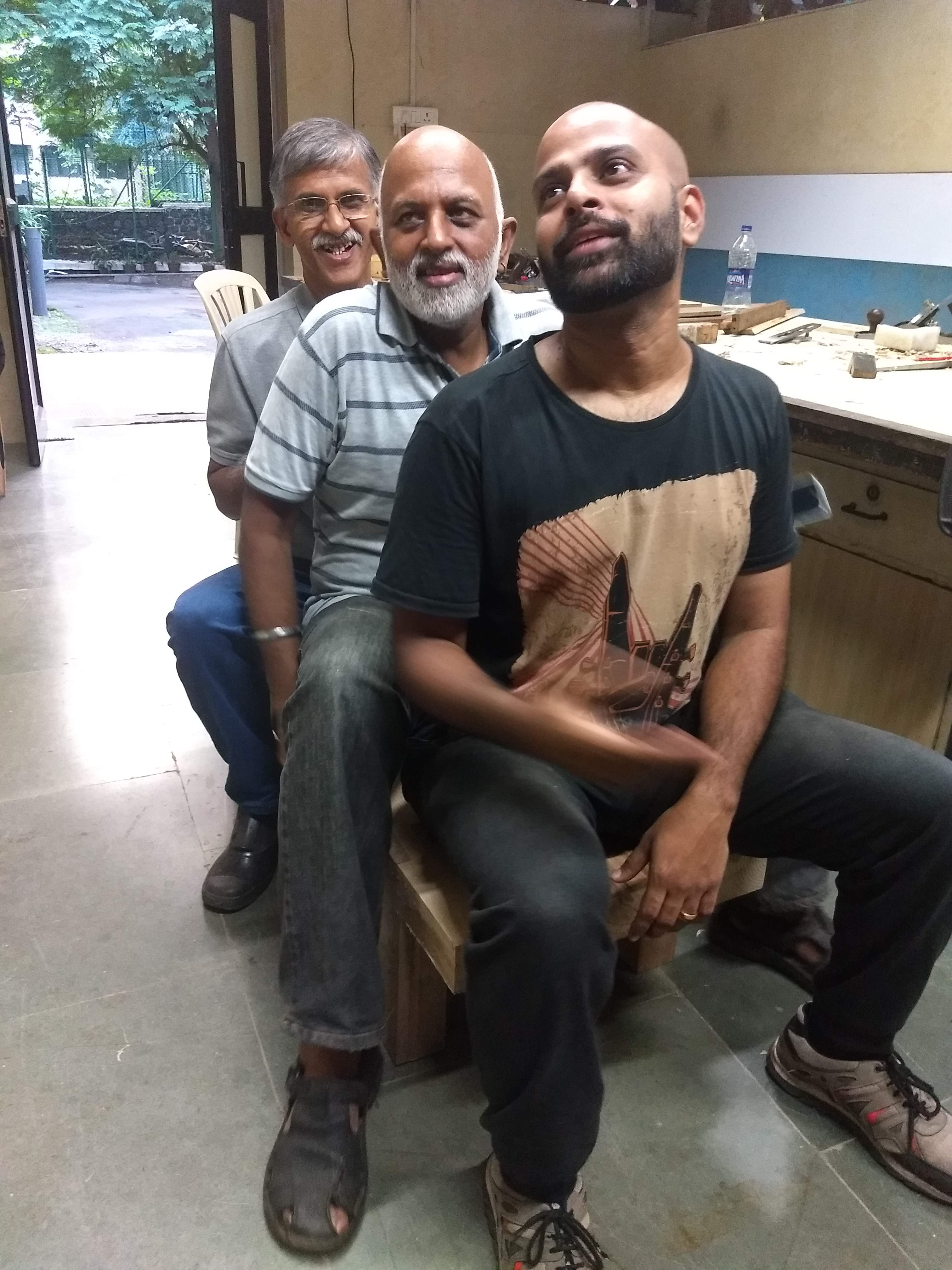
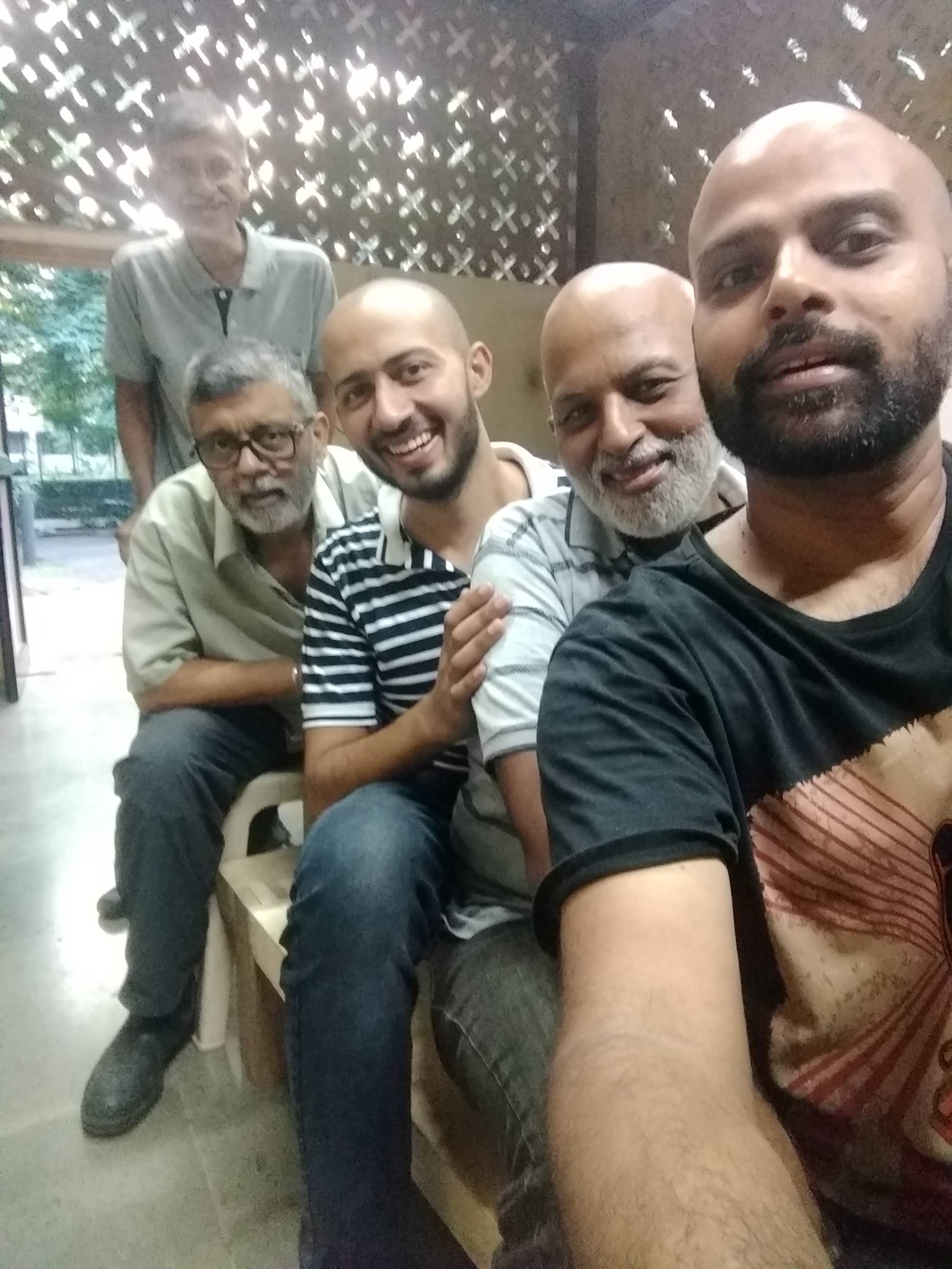
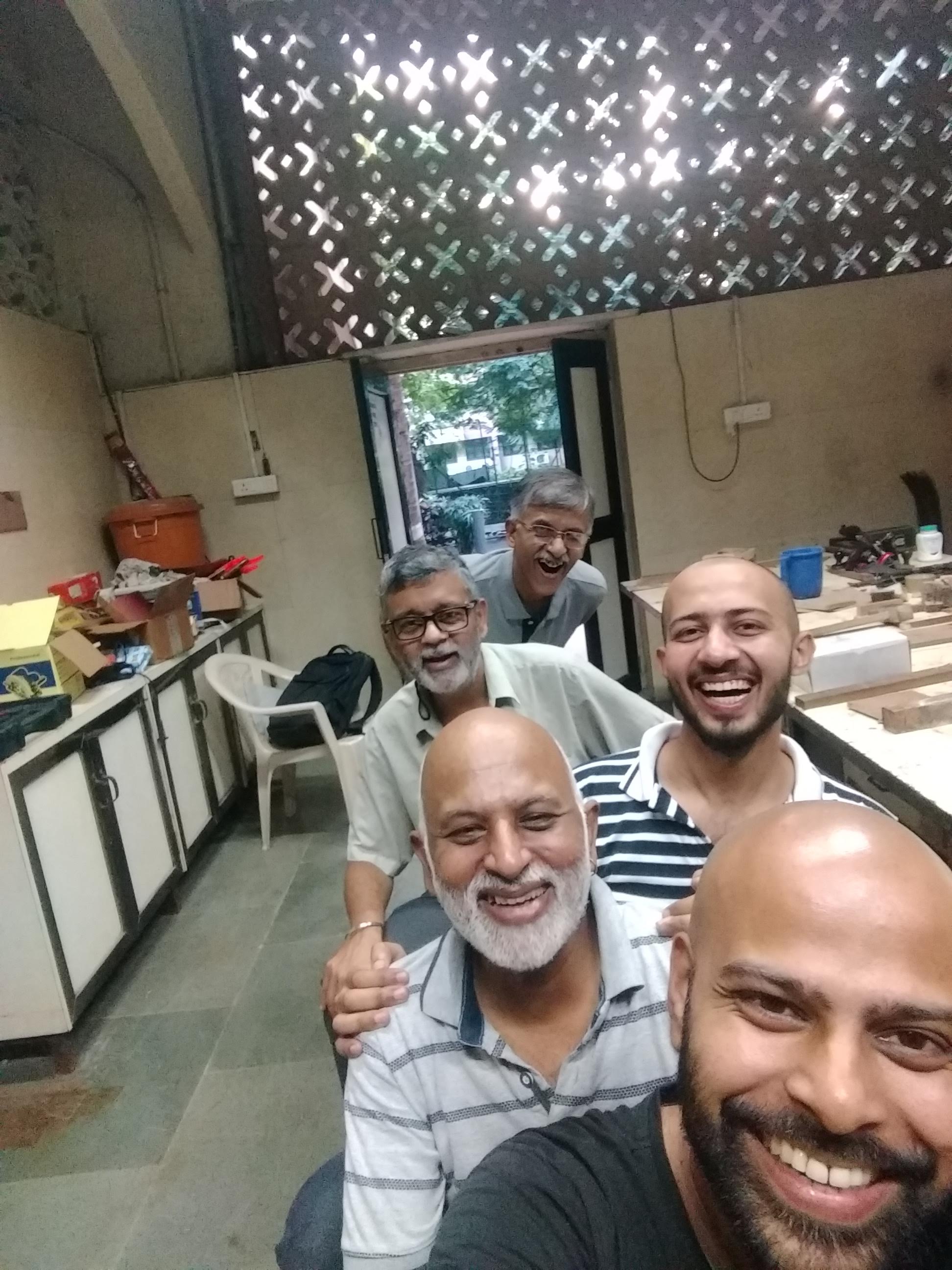
We would sincerely like to express the deepest gratitude to all the members who were involved in the project. Viren for being a superb mentor, Puneet for seeding the idea , Jude, GN, KS, VK, Ashish, Manoj, Shashank, Deborah, DP, Anil Sir, Cosmetic Staff, technical team, and all the other communities members for contributing in various capacities towards the completion of the project.
What’s next?
Use wood putty to fill in the cracks in the workbench - around the legs
I felt the need for a saw horse cum welding table. @Pneb wanted the working height different from what I need, the height has to be adjustable. Since the height has to be adjustable, might as well make it sufficiently adjustable to work standing or seated. Talk of feature creep!
Some images from the ongoing endeavor:
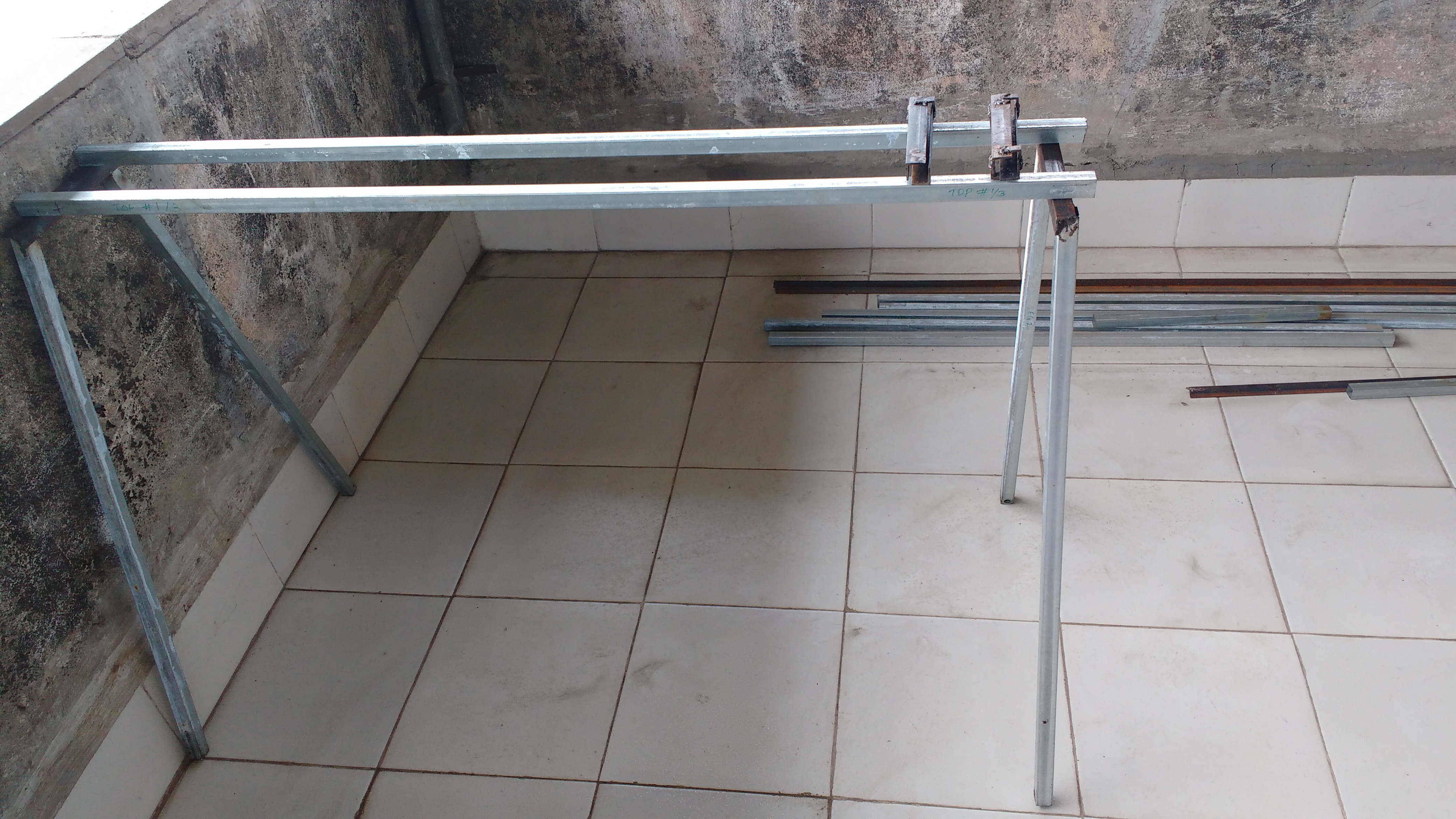
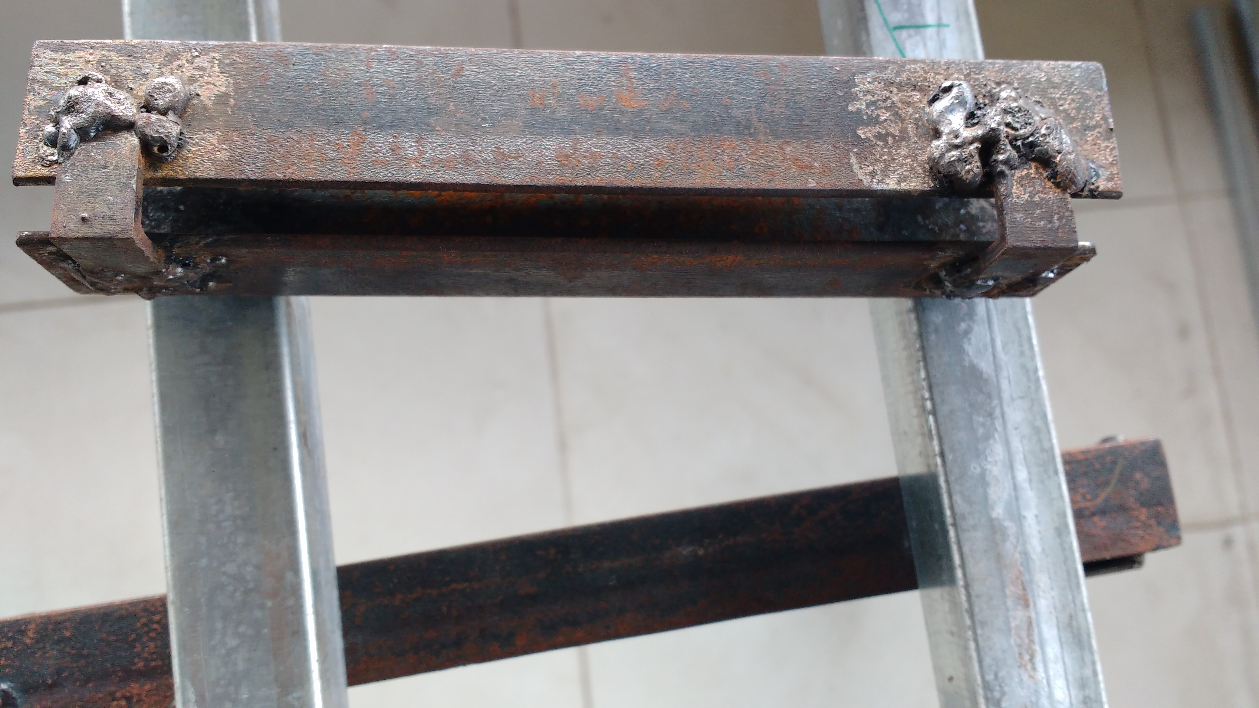
Legs with an angled cut of $11^o$ welded to the top.
Four of these will be used, 2 on each leg frame. Top frame will be fixed to the sliding section.
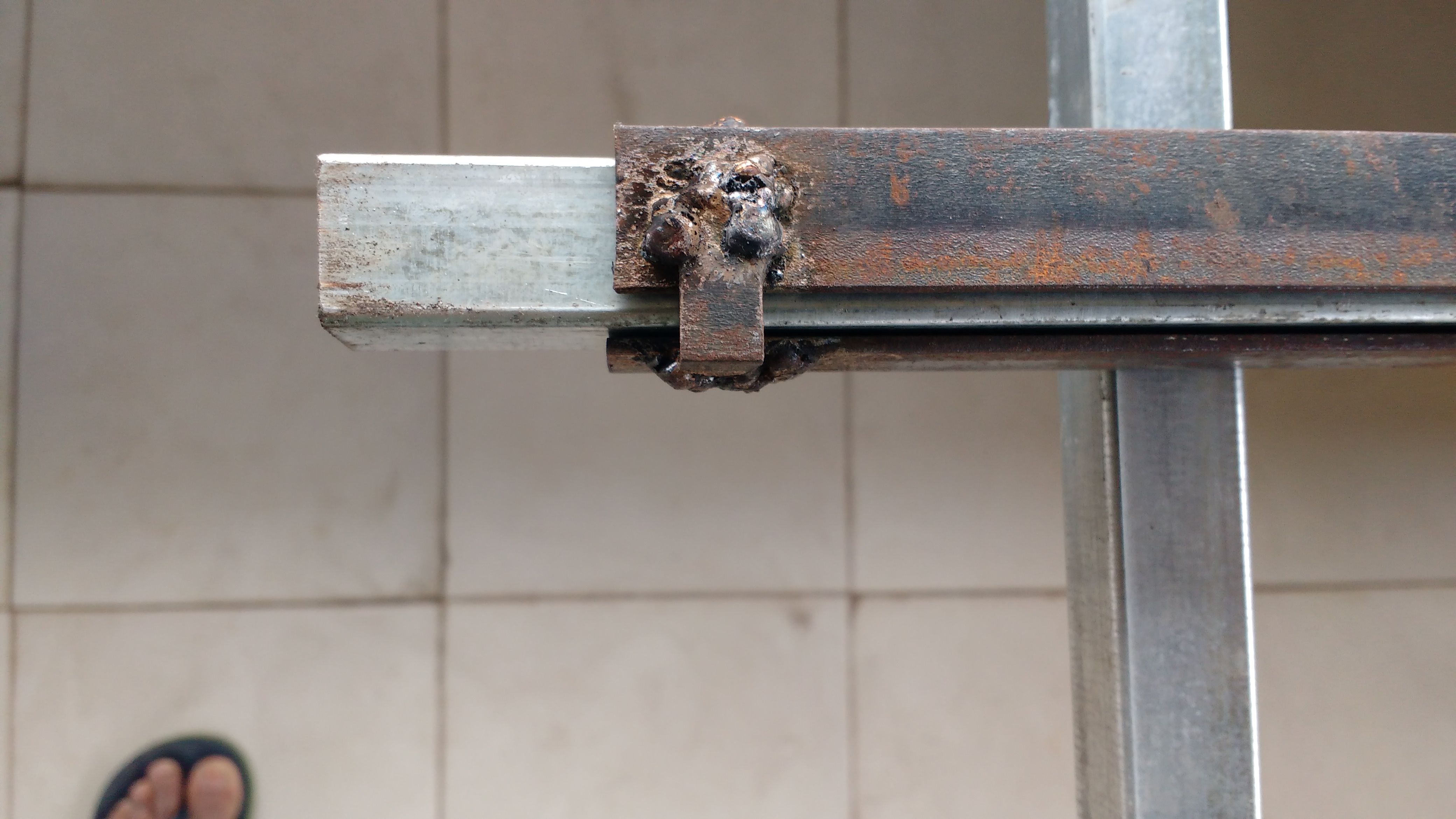
Four sockets are used to provide maximum stability. However that makes adjustment difficult if you are alone. Ideally a crank mechanism…feature creep again!
Notice the play at the end of the video? this will make the top shake approx 2 mm. The gap between slide and socket was created by wrapping some news paper around the slide - 3 layers. Which makes six layers on two opposite faces. Gap might be reduced by using only 2 layers in the rest of the sockets.
I think it might have been more practical to create a second height adjusting platform, with dogs to secure the saw frame.
By combining them or fiddling with a stable ‘horse’ (just couldn’t resist it ), a structure of good stability is being compromised.
A practical, although maybe more expensive in theory, very stable height adjusting platform for heavy duty work could be jerry rigged from an automobile hydraulic hand lift.
Ok. That should work too.
I wanted to avoid dogging, which would require my original socket arrangement, and instead just use two hydraulic jacks.
Come to think of it one would be less cumbersome than two jacks.
I realised that I don’t actually know the form factor of the lifts you found. Tyre puncture repairers usually use a trolley, which was in my mind when I commented. But there is also a simpler plain cylinder type. I haven’t checked the prices.
Anyhow, whichever is used, it is essential to have a single lever, so that the platform rises horizontally in a single action. I suspect that trying to make this happen with two (or four) jacks is going to be very, maybe unnecessarily, difficult.
Turns out that the car hydraulic jacks have limited vertical displacement of 12 to 16 cm. All vehicle jacks have this limit on displacement. I require a isplacement of approx 45cm.
Nonetheless an excellent, low cost and universally available method to make a lifting mechanism.
The difference for two persons is merely 10cm. But we need to work both standing and seated. Therefore the height varies from 75cm ± 10cm to 135cm ± 10cm.
I think a single cylinder car jack is probably about 20cm high with a throw of around 10cm. Together with a sturdy fixed platform, within another 10cm. So, two such adjustable platforms, 60cm total. Still cheap, stackable, and likely to be very sturdy, yet straightforward to build. And it gives you what you need, in straight steps of 30cm.
Which also means, you can stack them up against a wall when not in use, if you standardise each unit (2 lifts and the saw horse) to 30cm.
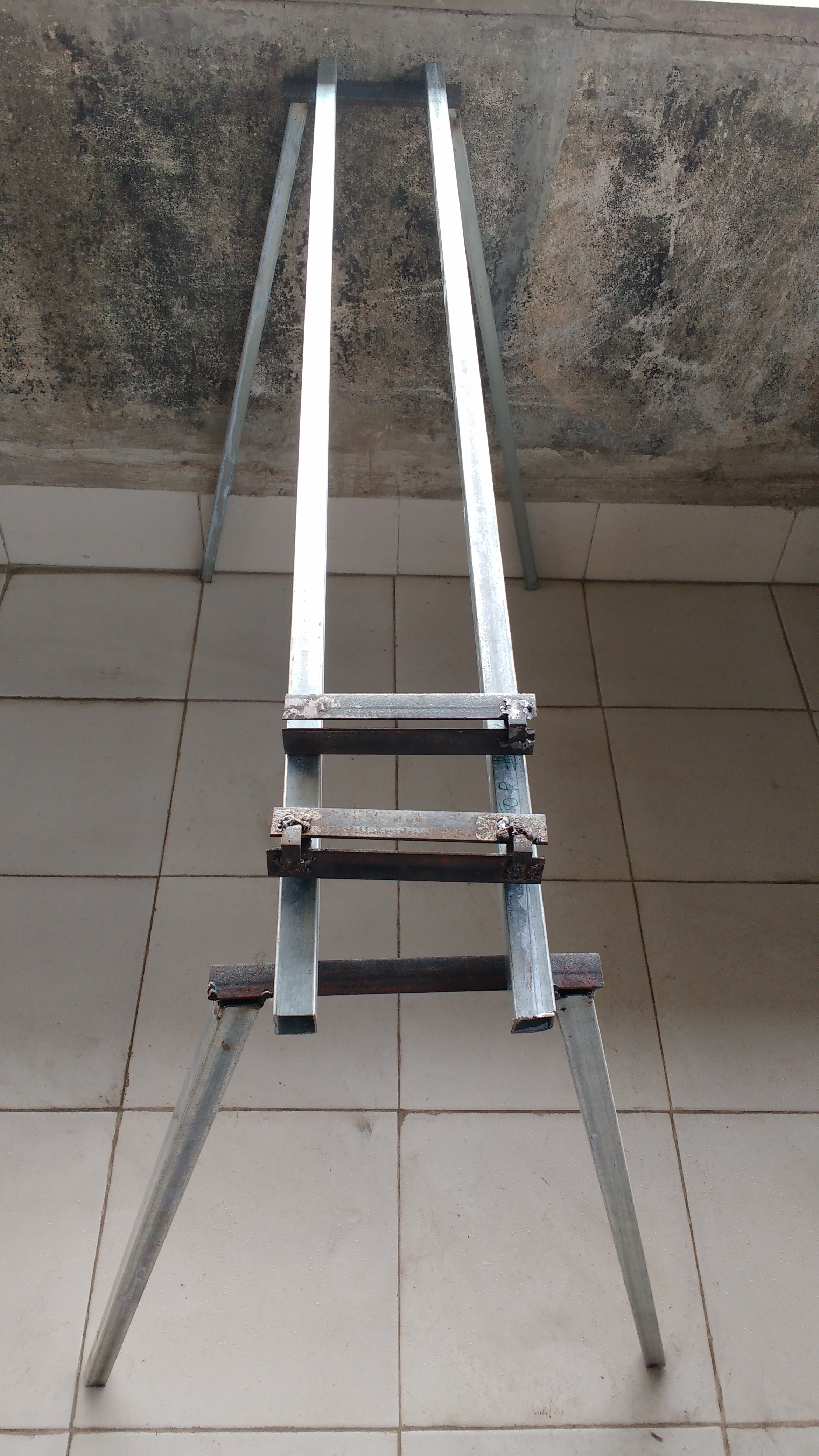
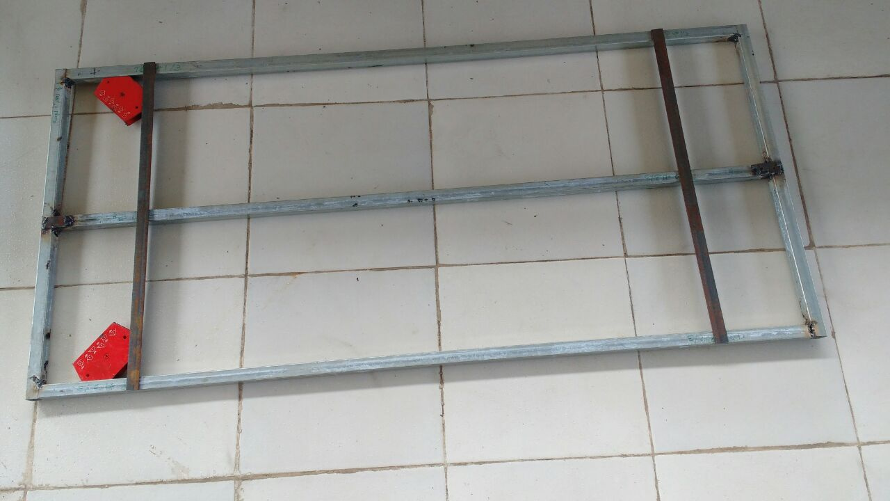
Top frame for saw horse is finally done. Today I am going to add the adjustable height pieces and complete the table. Additional cross members will be added too.
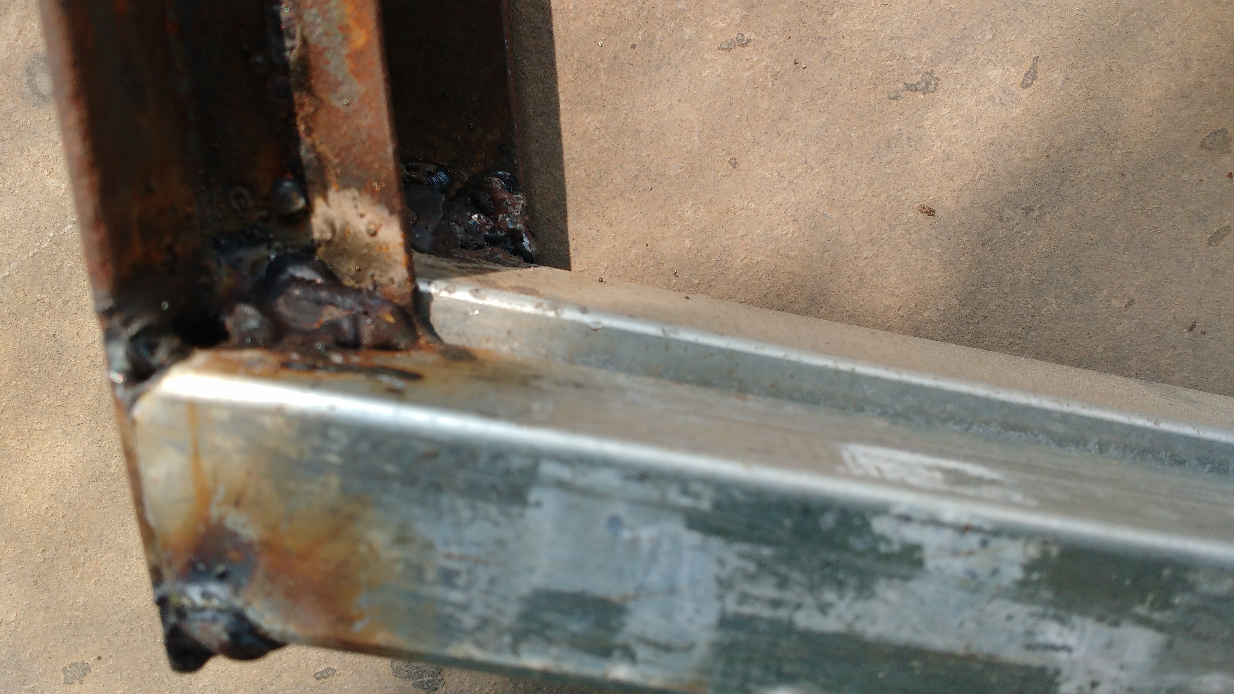
Welding the 17 gauge galvanised square sections is proving to be quite problematic. Firstly the arc burns the galvanised zinc, preventing the weld puddle from welding the two pieces. Next holding the weld rod for even a fraction of a sec longer burns the section. Hence I changed the support for the legs from square section to 2mm (14 swg) x 25mm L angle (the rusty looking strips, it being easier to weld. 2mm thick material welds ok with 2.5mm welding rods. Hereafter I will use a thicker section and ungalvanised. Ungalvanised means I will have to paint to prevent rusting.
Sourcing thicker square sections will be more difficult. It will also increase costs and weight.
I’m just guessing, but gas welding is probably more suited to galvanised sections. In fact, handheld propane or butane gas welding torches are available, that eliminate the nuisance of sourcing welding gas cylinders. The link is to a foreign store, but I’ve seen similar gadgets in local hardware shops.
In fact, referencing your other post on making diy imitation jewellery, these devices are very useful for that kind of project also.


